Information injection-pump assembly
ZEXEL
106691-0201
1066910201
Rating:
Cross reference number
ZEXEL
106691-0201
1066910201
Zexel num
Bosch num
Firm num
Name
106691-0201
INJECTION-PUMP ASSEMBLY
Calibration Data:
Adjustment conditions
Test oil
1404 Test oil ISO4113 or {SAEJ967d}
1404 Test oil ISO4113 or {SAEJ967d}
Test oil temperature
degC
40
40
45
Nozzle and nozzle holder
105780-8140
Bosch type code
EF8511/9A
Nozzle
105780-0000
Bosch type code
DN12SD12T
Nozzle holder
105780-2080
Bosch type code
EF8511/9
Opening pressure
MPa
17.2
Opening pressure
kgf/cm2
175
Injection pipe
Outer diameter - inner diameter - length (mm) mm 8-3-600
Outer diameter - inner diameter - length (mm) mm 8-3-600
Overflow valve (drive side)
134424-1720
Overflow valve opening pressure (drive side)
kPa
162
147
177
Overflow valve opening pressure (drive side)
kgf/cm2
1.65
1.5
1.8
Overflow valve (governor side)
132424-0620
Overflow valve opening pressure (governor side)
kPa
157
123
191
Overflow valve opening pressure (governor side)
kgf/cm2
1.6
1.25
1.95
Tester oil delivery pressure
kPa
157
157
157
Tester oil delivery pressure
kgf/cm2
1.6
1.6
1.6
Direction of rotation (viewed from drive side)
Right R
Right R
Injection timing adjustment
Direction of rotation (viewed from drive side)
Right R
Right R
Injection order
1-4-2-6-
3-5
Pre-stroke
mm
3.65
3.6
3.7
Beginning of injection position
Drive side NO.1
Drive side NO.1
Difference between angles 1
Cal 1-4 deg. 60 59.5 60.5
Cal 1-4 deg. 60 59.5 60.5
Difference between angles 2
Cyl.1-2 deg. 120 119.5 120.5
Cyl.1-2 deg. 120 119.5 120.5
Difference between angles 3
Cal 1-6 deg. 180 179.5 180.5
Cal 1-6 deg. 180 179.5 180.5
Difference between angles 4
Cal 1-3 deg. 240 239.5 240.5
Cal 1-3 deg. 240 239.5 240.5
Difference between angles 5
Cal 1-5 deg. 300 299.5 300.5
Cal 1-5 deg. 300 299.5 300.5
Injection quantity adjustment
Adjusting point
A
Rack position
11.1
Pump speed
r/min
650
650
650
Average injection quantity
mm3/st.
162
160
164
Max. variation between cylinders
%
0
-4
4
Basic
*
Fixing the lever
*
Boost pressure
kPa
30.7
30.7
Boost pressure
mmHg
230
230
Injection quantity adjustment_02
Adjusting point
B
Rack position
10.8+-0.
5
Pump speed
r/min
1100
1100
1100
Average injection quantity
mm3/st.
162.2
159.2
165.2
Max. variation between cylinders
%
0
-4
4
Fixing the lever
*
Boost pressure
kPa
30.7
30.7
Boost pressure
mmHg
230
230
Injection quantity adjustment_03
Adjusting point
C
Rack position
6+-0.5
Pump speed
r/min
250
250
250
Average injection quantity
mm3/st.
13.2
12.2
14.2
Max. variation between cylinders
%
0
-10
10
Fixing the rack
*
Boost pressure
kPa
0
0
0
Boost pressure
mmHg
0
0
0
Injection quantity adjustment_04
Adjusting point
D
Rack position
R1(9.5)
Pump speed
r/min
300
300
300
Average injection quantity
mm3/st.
112
109
115
Max. variation between cylinders
%
0
-4
4
Fixing the lever
*
Boost pressure
kPa
0
0
0
Boost pressure
mmHg
0
0
0
Injection quantity adjustment_05
Adjusting point
F
Rack position
R1+0.5++
Pump speed
r/min
40
40
40
Average injection quantity
mm3/st.
110
110
Fixing the lever
*
Boost pressure
kPa
0
0
0
Boost pressure
mmHg
0
0
0
Boost compensator adjustment
Pump speed
r/min
300
300
300
Rack position
R1(9.5)
Boost pressure
kPa
6.7
4
6.7
Boost pressure
mmHg
50
30
50
Boost compensator adjustment_02
Pump speed
r/min
300
300
300
Rack position
11.7
Boost pressure
kPa
24
Boost pressure
mmHg
180
Timer adjustment
Pump speed
r/min
200+100
Advance angle
deg.
1.6
1.1
2.1
Remarks
Start
Start
Timer adjustment_02
Pump speed
r/min
500-150
Advance angle
deg.
0
0
0
Timer adjustment_03
Pump speed
r/min
910+80
Advance angle
deg.
0
0
0
Timer adjustment_04
Pump speed
r/min
(1050)
Advance angle
deg.
2
1.5
2.5
Remarks
Finish
Finish
Test data Ex:
Governor adjustment
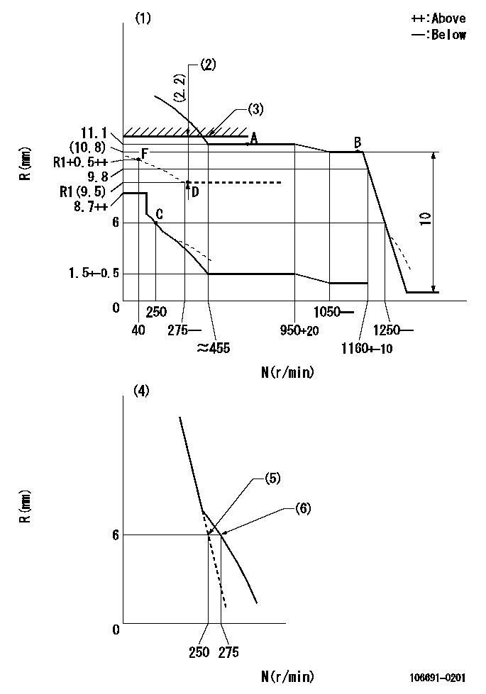
N:Pump speed
R:Rack position (mm)
(1)Damper spring setting: DL
(2)Boost compensator stroke
(3)Rack limit using the stop lever: R1
(4)Variable speed specification.
(5)Main spring setting
(6)Set idle sub-spring
----------
DL=5-0.2mm R1=11.7+-0.1mm
----------
----------
DL=5-0.2mm R1=11.7+-0.1mm
----------
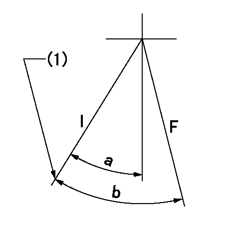
Speed control lever angle

F:Full speed
I:Idle
(1)Stopper bolt setting
----------
----------
a=10deg+-5deg b=26deg+-5deg
----------
----------
a=10deg+-5deg b=26deg+-5deg
0000000901
F:Full load
I:Idle
(1)Stopper bolt setting
----------
----------
a=20.5deg+-5deg b=35deg+-3deg
----------
----------
a=20.5deg+-5deg b=35deg+-3deg
Stop lever angle
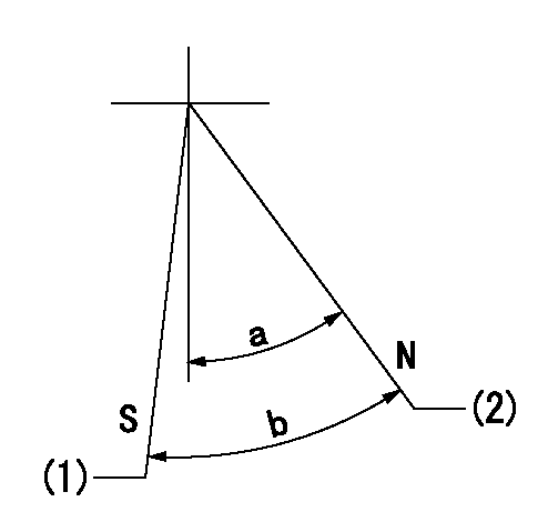
N:Pump normal
S:Stop the pump.
(1)Rack position = aa, speed = bb.
(2)Rack position = cc
----------
aa=1+0.5mm bb=0r/min cc=11.7mm
----------
a=28deg+-5deg b=30deg+-3deg
----------
aa=1+0.5mm bb=0r/min cc=11.7mm
----------
a=28deg+-5deg b=30deg+-3deg
0000001501 Q ADJUSTMENT PIPING
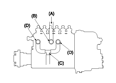
Tester fuel pipe A
Fuel inlet B
(C) Forked piping
(D) Overflow valve
Piping at standard injection quantity adjustment
1. Because the pump gallery is divided into two, be careful of the fuel piping at adjustment.
----------
----------
----------
----------
Timing setting

(1)Pump vertical direction
(2)Coupling's key groove position at No 1 cylinder's beginning of injection
(3)-
(4)-
----------
----------
a=(30deg)
----------
----------
a=(30deg)
Information:
Start By:a. remove cylinder head assemblyb. remove oil panc. remove piston cooling jets 1. Remove two rod cap bolts (1) from each rod. Remove rod caps (2).2. Using a soft jawed hammer, tap rod (3) away from the crankshaft. Remove bearing half (4).
When removing the cylinder pack, watch the rod, and prevent it from catching on the bore in the cylinder block as it comes out.
3. Install tooling (A), and remove cylinder pack (5). 4. Remove cylinder liner seal (6) at the base of the spacer block.5. Remove the remainder of tooling (A) from cylinder pack (5). 6. Remove the rod and piston from the cylinder liner. Remove seal (7) from the cylinder liner. The following steps are for the installation of the cylinder pack.7. Install a new cylinder liner seal (6) in the base of the spacer block. Lubricate the seal with clean engine oil. Some engines use pistons which have the word "FRONT" stamped on the crown of the piston. Be sure the word "FRONT" is toward the front of the engine when the piston is installed. The etched number on the connecting rod must be on the right side and must be installed in the corresponding cylinder. 9U-5839 Liquid Gasket Material is applied to the cylinder liners in the area shown in the illustration. The liquid gasket material helps prevent oil leaks from between the cylinder block and spacer block. DO NOT apply any 9U-5839 Liquid Gasket Material between the engine spacer block and the cylinder block surfaces. Using excessive amounts of liquid gasket material on the liner flange seat can cause oil leaks due to distortion of the O-ring seals between the spacer block and cylinder block.8. Install a new seal (7) on the cylinder liner.9. Lubricate the lower portion of the cylinder liner with clean engine oil. Be sure the corresponding crankshaft throw is at bottom center. Position cylinder pack (5), and guide rod (3) into place. Use tooling (B), and press cylinder pack (5) into place. Refer to the "Systems Operation Testing And Adjusting" module, Form No. SENR5561, for checking Cylinder Liner Projection.10. With rod (3) in this position, install the upper half of rod bearing (4). Be sure the bearing tab properly engages with the slot in the connecting rod. Lubricate the bearing surface with clean engine oil. Tap the piston down with a soft faced hammer until the rod and bearing contacts the crankshaft.11. With rod cap bearing in place and lubricated, install rod cap (2). Lubricate rod bolts (1) with 2P2506 Thread Lubricant. Install rod bolts (1), and tighten them to a torque of 130 7 N m (95 5 lb ft). Mark each bolt head, and tighten each bolt an additional 1/6 60 5 ( turn).End By:a. install piston cooling jetsb. install oil panc. install cylinder head assembly
Have questions with 106691-0201?
Group cross 106691-0201 ZEXEL
Nissan-Diesel
106691-0201
INJECTION-PUMP ASSEMBLY