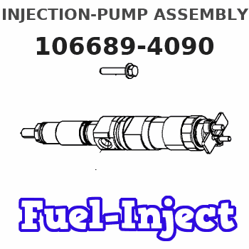
Information injection-pump assembly
BOSCH
9 400 612 762
9400612762
ZEXEL
106689-4090
1066894090
NIIGATA-URAWA
74W47100A
74w47100a
Rating:
Service parts 106689-4090 INJECTION-PUMP ASSEMBLY:
1.
_
4.
SUPPLY PUMP
5.
AUTOM. ADVANCE MECHANIS
7.
COUPLING PLATE
8.
_
9.
_
11.
Nozzle and Holder
74W 3227 1A
12.
Open Pre:MPa(Kqf/cm2)
31.4{320}
15.
NOZZLE SET
Include in #1:
106689-4090
as INJECTION-PUMP ASSEMBLY
Cross reference number
BOSCH
9 400 612 762
9400612762
ZEXEL
106689-4090
1066894090
NIIGATA-URAWA
74W47100A
74w47100a
Zexel num
Bosch num
Firm num
Name
Calibration Data:
Adjustment conditions
Test oil
1404 Test oil ISO4113 or {SAEJ967d}
1404 Test oil ISO4113 or {SAEJ967d}
Test oil temperature
degC
40
40
45
Nozzle and nozzle holder
105780-8130
Bosch type code
EFEP215A
Nozzle
105780-0050
Bosch type code
DN6TD119NP1T
Nozzle holder
105780-2090
Bosch type code
EFEP215
Opening pressure
MPa
17.2
Opening pressure
kgf/cm2
175
Injection pipe
Outer diameter - inner diameter - length (mm) mm 8-3-600
Outer diameter - inner diameter - length (mm) mm 8-3-600
Overflow valve
131425-1620
Overflow valve opening pressure
kPa
255
221
289
Overflow valve opening pressure
kgf/cm2
2.6
2.25
2.95
Tester oil delivery pressure
kPa
157
157
157
Tester oil delivery pressure
kgf/cm2
1.6
1.6
1.6
Direction of rotation (viewed from drive side)
Left L
Left L
Injection timing adjustment
Direction of rotation (viewed from drive side)
Left L
Left L
Injection order
1-4-2-6-
3-5
Pre-stroke
mm
3.5
3.45
3.55
Beginning of injection position
Drive side NO.1
Drive side NO.1
Difference between angles 1
Cal 1-4 deg. 60 59.5 60.5
Cal 1-4 deg. 60 59.5 60.5
Difference between angles 2
Cyl.1-2 deg. 120 119.5 120.5
Cyl.1-2 deg. 120 119.5 120.5
Difference between angles 3
Cal 1-6 deg. 180 179.5 180.5
Cal 1-6 deg. 180 179.5 180.5
Difference between angles 4
Cal 1-3 deg. 240 239.5 240.5
Cal 1-3 deg. 240 239.5 240.5
Difference between angles 5
Cal 1-5 deg. 300 299.5 300.5
Cal 1-5 deg. 300 299.5 300.5
Injection quantity adjustment
Adjusting point
A
Rack position
14.4
Pump speed
r/min
900
900
900
Average injection quantity
mm3/st.
344
339
349
Max. variation between cylinders
%
0
-3
3
Basic
*
Fixing the rack
*
Injection quantity adjustment_02
Adjusting point
B
Rack position
8.8+-0.5
Pump speed
r/min
250
250
250
Average injection quantity
mm3/st.
30
27
33
Max. variation between cylinders
%
0
-10
10
Fixing the rack
*
Injection quantity adjustment_03
Adjusting point
C
Rack position
16.4++
Pump speed
r/min
100
100
100
Average injection quantity
mm3/st.
350
340
360
Fixing the lever
*
Rack limit
*
Test data Ex:
Governor adjustment
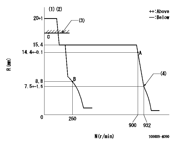
N:Pump speed
R:Rack position (mm)
(1)Target notch: K
(2)Tolerance for racks not indicated: +-0.05mm.
(3)RACK LIMIT
(4)Idle sub spring setting: L1.
----------
K=20 L1=7.5-0.5mm
----------
----------
K=20 L1=7.5-0.5mm
----------
Speed control lever angle
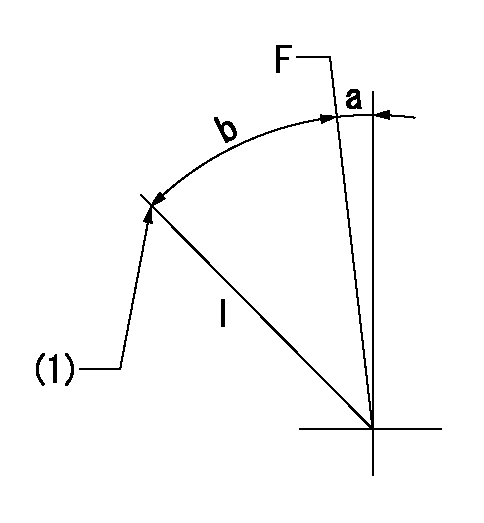
F:Full speed
I:Idle
(1)Stopper bolt setting
----------
----------
a=1deg+-5deg b=41deg+-5deg
----------
----------
a=1deg+-5deg b=41deg+-5deg
Stop lever angle
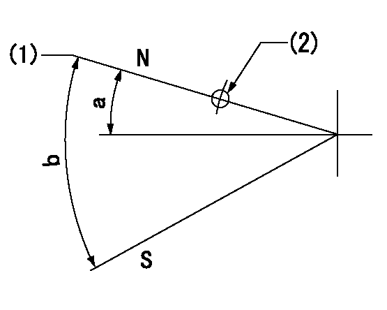
N:Pump normal
S:Stop the pump.
(1)Normal
(2)Use the hole at R = aa
----------
aa=17mm
----------
a=27deg+-5deg b=53deg+-5deg
----------
aa=17mm
----------
a=27deg+-5deg b=53deg+-5deg
Timing setting

(1)Pump vertical direction
(2)Coupling's key groove position at No 1 cylinder's beginning of injection
(3)-
(4)-
----------
----------
a=(6deg)
----------
----------
a=(6deg)
Information:
Electronic Controls
The electronic controller consists of two main components: the Electronic Control Module (ECM) and the Personality Module. The ECM is the computer which controls the PEEC engine. The Personality Module is the software which controls how the computer behaves. The two must be used together: neither can do anything by itself.Rack Controls
The rack mechanism on a PEEC III engine is very similar to a mechanical 3406B engine. The fuel injection pump is nearly identical; the rack is moved by a servo valve which receives oil pressure from the fuel injection pump. However, the PEEC III servo spool is moved by a solenoid or (BTM) rather than by a linkage controlled by flyweights and springs.PEEC III comes up with a "desired rpm" based on the throttle position, vehicle speed, customer specified parameters, and certain diagnostic codes. The PEEC III governor tries to maintain the desired rpm by sensing actual engine speed using the engine speed sensor, then controlling the rack to achieve the desired rpm. To move the rack, PEEC III adjusts the voltage to the rack solenoid (BTM) to increase rack. More voltage results in more rack. PEEC III knows how far the rack went by reading the rack position sensor. PEEC III increases the voltage to the rack solenoid until it senses the rack is in the desired position. PEEC III sets certain limits on rack motion. "FRC Rack" is a rack limit based on fuel-air ratio control, for emissions purposes. It works similar to a mechanical engine FRC; when PEEC III senses a higher boost pressure (more air into cylinder), it increases the FRC Rack limit, which allows more fuel into the cylinder. "Rated Rack" is a rack limit based on horsepower of the engine. It is similar to the rack stops and torque springs on a mechanical engine. It provides horsepower and torque curves for a specific engine family and rating. All of these limits are programmed by the factory into the personality module.Timing Advance Controls
The timing advance mechanism is the same as the 3406B mechanical engine, except the Timing solenoid (BTM), instead of the flyweights, controls timing advance. PEEC III adjusts voltage to the timing solenoid to change timing advance. More voltage results in more timing advance. PEEC III knows how much advance was achieved by reading the timing position sensor. PEEC III simply increases voltage to the timing solenoid until it senses that the timing advance is in the desired position. Programmable Parameters
Certain parameters that affect PEEC III 3406B Diesel Engine operation may be changed with electronic service tools (either the ECAP or DDT). The parameters are stored in the ECM, and are protected from unauthorized changes by passwords.These parameters are either "System Configuration Parameters" or "Customer Parameters". System Configuration Parameters are those that effect horsepower family or emissions. Customer Parameters are those that affect cruise control, vehicle speed limits, progressive shifting, horsepower rating within a family, and PTO operation.Some parameters may affect engine operation in ways a driver does not expect