Information injection-pump assembly
ZEXEL
106689-4080
1066894080

Rating:
Service parts 106689-4080 INJECTION-PUMP ASSEMBLY:
1.
_
3.
GOVERNOR
7.
COUPLING PLATE
8.
_
9.
_
11.
Nozzle and Holder
35A61-00010
12.
Open Pre:MPa(Kqf/cm2)
21.6{220}
15.
NOZZLE SET
Include in #1:
106689-4080
as INJECTION-PUMP ASSEMBLY
Cross reference number
ZEXEL
106689-4080
1066894080
Zexel num
Bosch num
Firm num
Name
106689-4080
INJECTION-PUMP ASSEMBLY
Calibration Data:
Adjustment conditions
Test oil
1404 Test oil ISO4113 or {SAEJ967d}
1404 Test oil ISO4113 or {SAEJ967d}
Test oil temperature
degC
40
40
45
Nozzle and nozzle holder
105780-8130
Bosch type code
EFEP215A
Nozzle
105780-0050
Bosch type code
DN6TD119NP1T
Nozzle holder
105780-2090
Bosch type code
EFEP215
Opening pressure
MPa
17.2
Opening pressure
kgf/cm2
175
Injection pipe
Outer diameter - inner diameter - length (mm) mm 8-4-1000
Outer diameter - inner diameter - length (mm) mm 8-4-1000
Overflow valve
131424-3420
Overflow valve opening pressure
kPa
255
221
289
Overflow valve opening pressure
kgf/cm2
2.6
2.25
2.95
Tester oil delivery pressure
kPa
157
157
157
Tester oil delivery pressure
kgf/cm2
1.6
1.6
1.6
Direction of rotation (viewed from drive side)
Left L
Left L
Injection timing adjustment
Direction of rotation (viewed from drive side)
Left L
Left L
Injection order
1-5-3-6-
2-4
Pre-stroke
mm
2.8
2.75
2.85
Rack position
Point A R=A
Point A R=A
Beginning of injection position
Opposite to the driving side NO.1
Opposite to the driving side NO.1
Difference between angles 1
Cal 1-5 deg. 60 59.5 60.5
Cal 1-5 deg. 60 59.5 60.5
Difference between angles 2
Cal 1-3 deg. 120 119.5 120.5
Cal 1-3 deg. 120 119.5 120.5
Difference between angles 3
Cal 1-6 deg. 180 179.5 180.5
Cal 1-6 deg. 180 179.5 180.5
Difference between angles 4
Cyl.1-2 deg. 240 239.5 240.5
Cyl.1-2 deg. 240 239.5 240.5
Difference between angles 5
Cal 1-4 deg. 300 299.5 300.5
Cal 1-4 deg. 300 299.5 300.5
Injection quantity adjustment
Adjusting point
A
Rack position
13
Pump speed
r/min
1000
1000
1000
Average injection quantity
mm3/st.
385
376
394
Max. variation between cylinders
%
0
-3
3
Basic
*
Fixing the rack
*
Rack limit
*
Injection quantity adjustment_02
Adjusting point
B
Rack position
6.6+-0.5
Pump speed
r/min
375
375
375
Average injection quantity
mm3/st.
10
7
13
Max. variation between cylinders
%
0
-10
10
Fixing the rack
*
Timer adjustment
Pump speed
r/min
(N1+50)-
-
Advance angle
deg.
0
0
0
Remarks
Start
Start
Timer adjustment_02
Pump speed
r/min
N1
Advance angle
deg.
0.5
Remarks
Measure the actual speed.
Measure the actual speed.
Timer adjustment_03
Pump speed
r/min
N2
Advance angle
deg.
4
3.5
4.5
Remarks
Measure the actual speed, stop
Measure the actual speed, stop
Test data Ex:
Timing setting
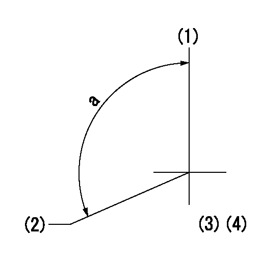
(1)Pump vertical direction
(2)Coupling's key groove position at No 1 cylinder's beginning of injection
(3)-
(4)-
----------
----------
a=(110deg)
----------
----------
a=(110deg)
Information:
On engines with serial numbers 7LG1-7499, Inlet Air Temperature Sensors have Deutsch HD Connectors, 7LG7500-UP Inlet Air Temperature Sensors have DT Connectors.Schematic
Diagnostic Codes
Functional Test
P-527: Oil Pressure Circuit Test
System Operation
The 3176 system monitors oil pressure with a sensor located in the oil gallery (right side of engine). The oil pressure sensor is supplied with electrical power by the 5 volt sensor supply voltage from the ECM. Note that the 3176 uses oil pressure only as an engine protection function (available for 7LG7500-UP engines). Lack of oil pressure does not prevent the 3176 ECM from starting the engine. The 3176 ECM will still try to start the engine even if oil pressure is low.The 3176 system monitors oil pressure following engine start up and may show a 100-01 Low Oil Pressure Warning Diagnostic Code (46). The Diagnostic Code will not be logged for the first 15 seconds following engine start up, only ACTIVE.The Oil Pressure Sensor can measure oil pressure from 0 kPa (0 psi) to 690 kPa (100 psi).The 3176 oil pressure sensor is supplied with electrical power by the 5 volt sensor supply voltage from the ECM through connector J4/P4 Pin 10 to the Oil Pressure Sensor Connector P17/J17 Pin A. The Oil Pressure Sensor signal line routes from P17/J17 Pin C to J4/P4 pin 27. The Sensor Common routes from J4/P4 Pin 35 to P17/J17 pin B. the +5 V supply is shared with the Coolant Temperature, Inlet Air Temperature, and Coolant Level (if installed) Sensors. The Sensor Common is shared by the Coolant Temperature, and Inlet Air Temperature Sensors.Schematic
Diagnostic Codes
Functional Test
ECAP Example Screen of Oil Pressure Reading P-528: Boost Pressure Circuit Test And Sensor Calibration
System Operation
The 3176 system monitors boost pressure with a sensor located inside the Transducer Module. The boost pressure sensor is supplied with electrical through the Transducer Module Connector (inside the module) pin 1 (+8V). The signal routes through pin 2 (Boost Pressure) and Sensor Common is pin 3. The sensor can only be replaced by replacing the transducer module.The boost pressure is used to reduce smoke emissions during acceleration. 3176 limits the amount of fuel injected until certain boost pressures are reached. It does this by converting boost pressure to "FRC Fuel Post." (as shown on the ECAP status display). The FRC Fuel Pos. is electronic limit on the amount of fuel injected and is based on a ratio of fuel to air being supplied to the cylinders. It operates in a manner similar to the fuel ratio control on an engine with a mechanical governor.The inlet air hose from the air cleaner to the transducer module must be installed. The air inlet serves as a vent for the transducer module and is required for proper operation of the boost pressure sensor.The 3176 Boost Pressure Sensor must be calibrated for a zero boost condition with the engine off. Calibration is accomplished electronically without the need for manual adjustments. The sensor must be recalibrated whenever the ECM or transducer module has
Diagnostic Codes
Functional Test
P-527: Oil Pressure Circuit Test
System Operation
The 3176 system monitors oil pressure with a sensor located in the oil gallery (right side of engine). The oil pressure sensor is supplied with electrical power by the 5 volt sensor supply voltage from the ECM. Note that the 3176 uses oil pressure only as an engine protection function (available for 7LG7500-UP engines). Lack of oil pressure does not prevent the 3176 ECM from starting the engine. The 3176 ECM will still try to start the engine even if oil pressure is low.The 3176 system monitors oil pressure following engine start up and may show a 100-01 Low Oil Pressure Warning Diagnostic Code (46). The Diagnostic Code will not be logged for the first 15 seconds following engine start up, only ACTIVE.The Oil Pressure Sensor can measure oil pressure from 0 kPa (0 psi) to 690 kPa (100 psi).The 3176 oil pressure sensor is supplied with electrical power by the 5 volt sensor supply voltage from the ECM through connector J4/P4 Pin 10 to the Oil Pressure Sensor Connector P17/J17 Pin A. The Oil Pressure Sensor signal line routes from P17/J17 Pin C to J4/P4 pin 27. The Sensor Common routes from J4/P4 Pin 35 to P17/J17 pin B. the +5 V supply is shared with the Coolant Temperature, Inlet Air Temperature, and Coolant Level (if installed) Sensors. The Sensor Common is shared by the Coolant Temperature, and Inlet Air Temperature Sensors.Schematic
Diagnostic Codes
Functional Test
ECAP Example Screen of Oil Pressure Reading P-528: Boost Pressure Circuit Test And Sensor Calibration
System Operation
The 3176 system monitors boost pressure with a sensor located inside the Transducer Module. The boost pressure sensor is supplied with electrical through the Transducer Module Connector (inside the module) pin 1 (+8V). The signal routes through pin 2 (Boost Pressure) and Sensor Common is pin 3. The sensor can only be replaced by replacing the transducer module.The boost pressure is used to reduce smoke emissions during acceleration. 3176 limits the amount of fuel injected until certain boost pressures are reached. It does this by converting boost pressure to "FRC Fuel Post." (as shown on the ECAP status display). The FRC Fuel Pos. is electronic limit on the amount of fuel injected and is based on a ratio of fuel to air being supplied to the cylinders. It operates in a manner similar to the fuel ratio control on an engine with a mechanical governor.The inlet air hose from the air cleaner to the transducer module must be installed. The air inlet serves as a vent for the transducer module and is required for proper operation of the boost pressure sensor.The 3176 Boost Pressure Sensor must be calibrated for a zero boost condition with the engine off. Calibration is accomplished electronically without the need for manual adjustments. The sensor must be recalibrated whenever the ECM or transducer module has
Have questions with 106689-4080?
Group cross 106689-4080 ZEXEL
Daihatsu
Komatsu
Komatsu
Mitsubishi-Heav
Komatsu
Mitsubishi-Heav
Mitsubishi-Heav
Komatsu
106689-4080
INJECTION-PUMP ASSEMBLY