Information injection-pump assembly
BOSCH
F 019 Z20 224
f019z20224
ZEXEL
106685-4540
1066854540
MITSUBISHI-HEAV
35A6540130
35a6540130

Rating:
Service parts 106685-4540 INJECTION-PUMP ASSEMBLY:
1.
_
5.
AUTOM. ADVANCE MECHANIS
8.
_
9.
_
11.
Nozzle and Holder
12.
Open Pre:MPa(Kqf/cm2)
29.4(300)
15.
NOZZLE SET
Include in #1:
106685-4540
as INJECTION-PUMP ASSEMBLY
Cross reference number
BOSCH
F 019 Z20 224
f019z20224
ZEXEL
106685-4540
1066854540
MITSUBISHI-HEAV
35A6540130
35a6540130
Zexel num
Bosch num
Firm num
Name
106685-4540
F 019 Z20 224
35A6540130 MITSUBISHI-HEAV
INJECTION-PUMP ASSEMBLY
S6B3-MPTA K 14CA INJECTION PUMP ASSY PE6P,6PD PE
S6B3-MPTA K 14CA INJECTION PUMP ASSY PE6P,6PD PE
Calibration Data:
Adjustment conditions
Test oil
1404 Test oil ISO4113 or {SAEJ967d}
1404 Test oil ISO4113 or {SAEJ967d}
Test oil temperature
degC
40
40
45
Nozzle and nozzle holder
105780-8130
Bosch type code
EFEP215A
Nozzle
105780-0050
Bosch type code
DN6TD119NP1T
Nozzle holder
105780-2090
Bosch type code
EFEP215
Opening pressure
MPa
17.2
Opening pressure
kgf/cm2
175
Injection pipe
Outer diameter - inner diameter - length (mm) mm 8-4-1000
Outer diameter - inner diameter - length (mm) mm 8-4-1000
Overflow valve
131424-3420
Overflow valve opening pressure
kPa
255
221
289
Overflow valve opening pressure
kgf/cm2
2.6
2.25
2.95
Tester oil delivery pressure
kPa
157
157
157
Tester oil delivery pressure
kgf/cm2
1.6
1.6
1.6
Direction of rotation (viewed from drive side)
Left L
Left L
Injection timing adjustment
Direction of rotation (viewed from drive side)
Left L
Left L
Injection order
1-5-3-6-
2-4
Pre-stroke
mm
2.8
2.75
2.85
Beginning of injection position
Governor side NO.1
Governor side NO.1
Difference between angles 1
Cal 1-5 deg. 60 59.5 60.5
Cal 1-5 deg. 60 59.5 60.5
Difference between angles 2
Cal 1-3 deg. 120 119.5 120.5
Cal 1-3 deg. 120 119.5 120.5
Difference between angles 3
Cal 1-6 deg. 180 179.5 180.5
Cal 1-6 deg. 180 179.5 180.5
Difference between angles 4
Cyl.1-2 deg. 240 239.5 240.5
Cyl.1-2 deg. 240 239.5 240.5
Difference between angles 5
Cal 1-4 deg. 300 299.5 300.5
Cal 1-4 deg. 300 299.5 300.5
Injection quantity adjustment
Adjusting point
A
Rack position
14.1
Pump speed
r/min
1035
1035
1035
Average injection quantity
mm3/st.
459
450
468
Max. variation between cylinders
%
0
-3
3
Basic
*
Fixing the lever
*
Boost pressure
kPa
137
137
Boost pressure
mmHg
1030
1030
Injection quantity adjustment_02
Adjusting point
C
Rack position
6.8+-0.5
Pump speed
r/min
300
300
300
Average injection quantity
mm3/st.
37
34
40
Max. variation between cylinders
%
0
-10
10
Fixing the rack
*
Boost pressure
kPa
0
0
0
Boost pressure
mmHg
0
0
0
Boost compensator adjustment
Pump speed
r/min
750
750
750
Rack position
R1-3.2
Boost pressure
kPa
62.7
60
65.4
Boost pressure
mmHg
470
450
490
Boost compensator adjustment_02
Pump speed
r/min
750
750
750
Rack position
R1(14.1)
Boost pressure
kPa
124
117.3
130.7
Boost pressure
mmHg
930
880
980
Test data Ex:
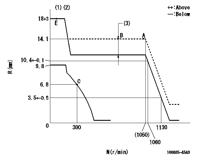
Governor adjustment

N:Pump speed
R:Rack position (mm)
(1)Target notch: K
(2)Tolerance for racks not indicated: +-0.05mm.
(3)Boost compensator stroke: BCL
----------
K=19 BCL=3.2+-0.1mm
----------
----------
K=19 BCL=3.2+-0.1mm
----------
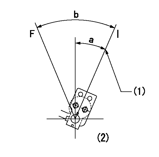
Speed control lever angle

F:Full speed
I:Idle
(1)Stopper bolt setting
(2)At the center of the lever key groove
----------
----------
a=(26deg)+-5deg b=(40deg)+-5deg
----------
----------
a=(26deg)+-5deg b=(40deg)+-5deg
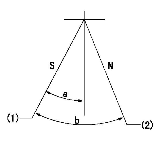
Stop lever angle

N:Pump normal
S:Stop the pump.
(1)Pump speed aa, rack position bb
(2)Normal
----------
aa=0r/min bb=1-0.5mm
----------
a=33deg+-5deg b=(73deg)
----------
aa=0r/min bb=1-0.5mm
----------
a=33deg+-5deg b=(73deg)
Timing setting

(1)Pump vertical direction
(2)Coupling's key groove position at No 1 cylinder's beginning of injection
(3)-
(4)-
----------
----------
a=(20deg)
----------
----------
a=(20deg)
Information:
1. Once all connections have been checked, energize the system.A) The RED indicator light should come on. This indicates that the control is 'OFF'.*... If the LO indicator light is 'ON', it indicates an open connection on the BLUE output wire going to the center solenoid.... If the MED indicator light is 'ON', it indicates an open connection on the YELLOW output wire going to the front and/or rear solenoids*If the RED light starts to flash: This indicates that there is an open connection on the output.If an open connection occurs, insure that there is a good connection at the solenoid, and at the output of the control module. If there is still a problem remove the harness connections on the 002299 terminal leadout. Measure the resistance of the solenoid at the 002299 terminal leadout on the Jake Brake housing (+ probe on the 002299 terminal, - probe to ground). The ohmmeter should read between 7 and 14 ohms. If it does not, replace the solenoid. If the problem still occurs, replace the suspected output wire, and insure a good connection
Have questions with 106685-4540?
Group cross 106685-4540 ZEXEL
Komatsu
Mitsubishi-Heav
106685-4540
F 019 Z20 224
35A6540130
INJECTION-PUMP ASSEMBLY
S6B3-MPTA
S6B3-MPTA