Information injection-pump assembly
BOSCH
9 400 613 446
9400613446
ZEXEL
106685-4481
1066854481
KOMATSU
6212721110
6212721110
Rating:
Compare Prices: .
As an associate, we earn commssions on qualifying purchases through the links below

VIIKEND Fuel Injection Pump 6212-72-1110 R6212721110 6212-72-1111 Compatible with Komatsu D-275A-5D Engine SDA6D140E-2E-9
VIIKEND Part Name: Fuel Injection Pump || Part Number: 6212-72-1110 R6212721110 Note: Please check the fitment carefully before purchase. Or just tell us the part number you need. || Engine Model: SDA6D140E-2E-9 || Applicable: Compatible with Komatsu D-275A-5D Engine SDA6D140E-2E-9 || Package included: 1pcs Fuel Injection Pump 6212-72-1110 R6212721110 6212-72-1111
VIIKEND Part Name: Fuel Injection Pump || Part Number: 6212-72-1110 R6212721110 Note: Please check the fitment carefully before purchase. Or just tell us the part number you need. || Engine Model: SDA6D140E-2E-9 || Applicable: Compatible with Komatsu D-275A-5D Engine SDA6D140E-2E-9 || Package included: 1pcs Fuel Injection Pump 6212-72-1110 R6212721110 6212-72-1111

Aftermarket Fuel Injection Pump 6212-72-1110 DK106068-4210 Fit Intended For Engine SDA6D140E-2E-9
Generic Motorcycle Parts || Heavy Equipment Parts || Spare Parts || Fuel Systems
Generic Motorcycle Parts || Heavy Equipment Parts || Spare Parts || Fuel Systems

Service parts 106685-4481 INJECTION-PUMP ASSEMBLY:
1.
_
5.
AUTOM. ADVANCE MECHANIS
7.
COUPLING PLATE
8.
_
9.
_
11.
Nozzle and Holder
12.
Open Pre:MPa(Kqf/cm2)
24.5{250}
15.
NOZZLE SET
Include in #1:
106685-4481
as INJECTION-PUMP ASSEMBLY
Cross reference number
BOSCH
9 400 613 446
9400613446
ZEXEL
106685-4481
1066854481
KOMATSU
6212721110
6212721110
Zexel num
Bosch num
Firm num
Name
106685-4481
9 400 613 446
6212721110 KOMATSU
INJECTION-PUMP ASSEMBLY
SDA6D140 K 14CA INJECTION PUMP ASSY PE6P,6PD PE
SDA6D140 K 14CA INJECTION PUMP ASSY PE6P,6PD PE
Calibration Data:
Adjustment conditions
Test oil
1404 Test oil ISO4113 or {SAEJ967d}
1404 Test oil ISO4113 or {SAEJ967d}
Test oil temperature
degC
40
40
45
Nozzle and nozzle holder
105780-8130
Bosch type code
EFEP215A
Nozzle
105780-0050
Bosch type code
DN6TD119NP1T
Nozzle holder
105780-2090
Bosch type code
EFEP215
Opening pressure
MPa
17.2
Opening pressure
kgf/cm2
175
Injection pipe
Outer diameter - inner diameter - length (mm) mm 8-4-1000
Outer diameter - inner diameter - length (mm) mm 8-4-1000
Overflow valve
131425-1620
Overflow valve opening pressure
kPa
255
221
289
Overflow valve opening pressure
kgf/cm2
2.6
2.25
2.95
Tester oil delivery pressure
kPa
255
255
255
Tester oil delivery pressure
kgf/cm2
2.6
2.6
2.6
Direction of rotation (viewed from drive side)
Right R
Right R
Injection timing adjustment
Direction of rotation (viewed from drive side)
Right R
Right R
Injection order
1-5-3-6-
2-4
Pre-stroke
mm
3.3
3.25
3.35
Beginning of injection position
Drive side NO.1
Drive side NO.1
Difference between angles 1
Cal 1-5 deg. 60 59.5 60.5
Cal 1-5 deg. 60 59.5 60.5
Difference between angles 2
Cal 1-3 deg. 120 119.5 120.5
Cal 1-3 deg. 120 119.5 120.5
Difference between angles 3
Cal 1-6 deg. 180 179.5 180.5
Cal 1-6 deg. 180 179.5 180.5
Difference between angles 4
Cyl.1-2 deg. 240 239.5 240.5
Cyl.1-2 deg. 240 239.5 240.5
Difference between angles 5
Cal 1-4 deg. 300 299.5 300.5
Cal 1-4 deg. 300 299.5 300.5
Injection quantity adjustment
Adjusting point
A
Rack position
11.8
Pump speed
r/min
1000
1000
1000
Average injection quantity
mm3/st.
308
303
313
Max. variation between cylinders
%
0
-3
3
Basic
*
Fixing the lever
*
Boost pressure
kPa
84
84
Boost pressure
mmHg
630
630
Injection quantity adjustment_02
Adjusting point
B
Rack position
7.7+-0.5
Pump speed
r/min
350
350
350
Average injection quantity
mm3/st.
19
17.5
20.5
Max. variation between cylinders
%
0
-15
15
Fixing the rack
*
Boost pressure
kPa
0
0
0
Boost pressure
mmHg
0
0
0
Injection quantity adjustment_03
Adjusting point
D
Rack position
12++
Pump speed
r/min
100
100
100
Average injection quantity
mm3/st.
275
265
285
Fixing the lever
*
Boost pressure
kPa
0
0
0
Boost pressure
mmHg
0
0
0
Rack limit
*
Boost compensator adjustment
Pump speed
r/min
600
600
600
Rack position
R1-2
Boost pressure
kPa
32
29.3
34.7
Boost pressure
mmHg
240
220
260
Boost compensator adjustment_02
Pump speed
r/min
600
600
600
Rack position
R1(12.7)
Boost pressure
kPa
70.6
70.6
70.6
Boost pressure
mmHg
530
530
530
Test data Ex:
Governor adjustment
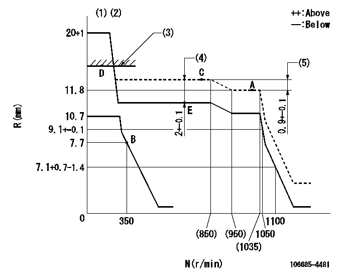
N:Pump speed
R:Rack position (mm)
(1)Target notch: K
(2)Tolerance for racks not indicated: +-0.05mm.
(3)RACK LIMIT
(4)Boost compensator stroke
(5)Rack difference between N = N1 and N = N2
----------
K=22 N1=1000r/min N2=700r/min
----------
----------
K=22 N1=1000r/min N2=700r/min
----------
Speed control lever angle
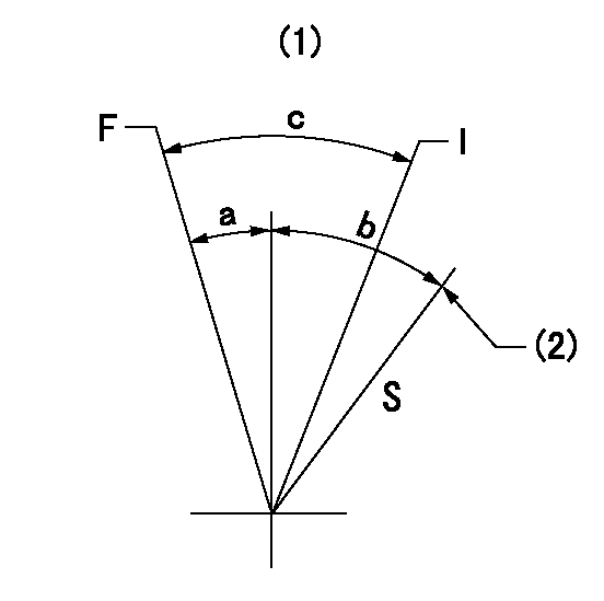
F:Full speed
I:Idle
S:Stop
(1)Base lever only
(2)Stopper bolt setting
----------
----------
a=27deg+-5deg b=36deg+-3deg c=37deg+-5deg
----------
----------
a=27deg+-5deg b=36deg+-3deg c=37deg+-5deg
0000001501 GOVERNOR IDLE SUB SPRING
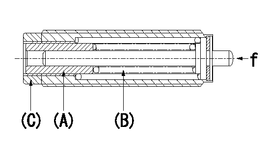
f : Installation load ON
2 stage idle sub-spring simultaneous setting method
1. (1) Remove the idling sub spring capsule from the governor.
(2)Tighten the screw (A) until it contacts the spring (B) (that is, until the set force is generated).
(3)Return to speed N1.
(4)Set so that the set force is zero.
(5)Fix using the lock nut (C).
2. Set the idle sub spring capsule adjusted as per (1) 1.
(2)Same as the normal 1 stage idle sub spring.
(3)Set so that it satisfies the governor adjustment standards.
(4)Do not loosen lock nut (C) at this time.
----------
N1=1/2
----------
----------
N1=1/2
----------
Timing setting

(1)Pump vertical direction
(2)Coupling's key groove position at No 1 cylinder's beginning of injection
(3)B.T.D.C.: aa
(4)-
----------
aa=19deg
----------
a=(10deg)
----------
aa=19deg
----------
a=(10deg)
Information:
Overcooling
25. Defective Temperature GaugeIf the temperature gauge shows that the coolant temperature is below normal and all other conditions indicate that conditions are normal, check the coolant temperature in another method, such as:* Read the coolant temperature with an ECAP or DDT.* Install an 8T0470 Thermistor Thermometer Group* Install a temperature sensitive tape.* Install a new gauge that is known to be good.26. Defective Coolant Temperature SensorIf a fault is detected in the coolant temperature sensor circuit, determine if the fault is in the wiring or the coolant temperature sensor following the procedure in Electronic Troubleshooting, 3176 Diesel Truck Engine, Form No. SENR3913. Repair or replace parts as needed. The coolant temperature sensor should be accurate within plus or minus 3° C (6° F). Check the accuracy of the sensor if it is found to be out of specification.27. Long Idle PeriodsRunning the engine for extended periods of time under no load conditions will cause the engine heat to be removed at a faster rate than it is being generated.28. Very Light LoadsVery light loads, very slow speeds, or downhill travel can cause below normal heating due to the decreased amount of fuel that is being burned. The installation of shutters will help correct this problem by decreasing the flow of air into the engine compartment.29. Defective Water Temperature RegulatorIf the water temperature regulator is stuck open, it will cause below normal engine heating. To test the thermostat, see the topic, Testing The Cooling System, in the Testing and Adjusting section of Systems Operation, Testing and Adjusting, Form No. SENR3909.30. Faulty Fan Clutch (Will Not Disengage)Check for proper operation of the fan clutch. Refer to the Truck Manufacturer's Service Manual for the proper procedure.31. Vent Line OpenIf the vent line (OEM) between the temperature regulator and the radiator top tank is open, overcooling could result. Install a valve assembly in the line that will allow air venting but restrict coolant flow with the engine running.
25. Defective Temperature GaugeIf the temperature gauge shows that the coolant temperature is below normal and all other conditions indicate that conditions are normal, check the coolant temperature in another method, such as:* Read the coolant temperature with an ECAP or DDT.* Install an 8T0470 Thermistor Thermometer Group* Install a temperature sensitive tape.* Install a new gauge that is known to be good.26. Defective Coolant Temperature SensorIf a fault is detected in the coolant temperature sensor circuit, determine if the fault is in the wiring or the coolant temperature sensor following the procedure in Electronic Troubleshooting, 3176 Diesel Truck Engine, Form No. SENR3913. Repair or replace parts as needed. The coolant temperature sensor should be accurate within plus or minus 3° C (6° F). Check the accuracy of the sensor if it is found to be out of specification.27. Long Idle PeriodsRunning the engine for extended periods of time under no load conditions will cause the engine heat to be removed at a faster rate than it is being generated.28. Very Light LoadsVery light loads, very slow speeds, or downhill travel can cause below normal heating due to the decreased amount of fuel that is being burned. The installation of shutters will help correct this problem by decreasing the flow of air into the engine compartment.29. Defective Water Temperature RegulatorIf the water temperature regulator is stuck open, it will cause below normal engine heating. To test the thermostat, see the topic, Testing The Cooling System, in the Testing and Adjusting section of Systems Operation, Testing and Adjusting, Form No. SENR3909.30. Faulty Fan Clutch (Will Not Disengage)Check for proper operation of the fan clutch. Refer to the Truck Manufacturer's Service Manual for the proper procedure.31. Vent Line OpenIf the vent line (OEM) between the temperature regulator and the radiator top tank is open, overcooling could result. Install a valve assembly in the line that will allow air venting but restrict coolant flow with the engine running.
Have questions with 106685-4481?
Group cross 106685-4481 ZEXEL
Komatsu
Mitsubishi-Heav
Komatsu
Komatsu
Komatsu
106685-4481
9 400 613 446
6212721110
INJECTION-PUMP ASSEMBLY
SDA6D140
SDA6D140