Information injection-pump assembly
BOSCH
9 400 617 732
9400617732
ZEXEL
106685-4460
1066854460
KOMATSU
6162751610
6162751610
Rating:
Cross reference number
BOSCH
9 400 617 732
9400617732
ZEXEL
106685-4460
1066854460
KOMATSU
6162751610
6162751610
Zexel num
Bosch num
Firm num
Name
106685-4460
9 400 617 732
6162751610 KOMATSU
INJECTION-PUMP ASSEMBLY
SA6D170 K
SA6D170 K
Calibration Data:
Adjustment conditions
Test oil
1404 Test oil ISO4113 or {SAEJ967d}
1404 Test oil ISO4113 or {SAEJ967d}
Test oil temperature
degC
40
40
45
Nozzle and nozzle holder
105780-8130
Bosch type code
EFEP215A
Nozzle
105780-0050
Bosch type code
DN6TD119NP1T
Nozzle holder
105780-2090
Bosch type code
EFEP215
Opening pressure
MPa
17.2
Opening pressure
kgf/cm2
175
Injection pipe
Outer diameter - inner diameter - length (mm) mm 8-4-1000
Outer diameter - inner diameter - length (mm) mm 8-4-1000
Overflow valve
131425-1620
Overflow valve opening pressure
kPa
255
255
255
Overflow valve opening pressure
kgf/cm2
2.6
2.6
2.6
Tester oil delivery pressure
kPa
255
255
255
Tester oil delivery pressure
kgf/cm2
2.6
2.6
2.6
Direction of rotation (viewed from drive side)
Left L
Left L
Injection timing adjustment
Direction of rotation (viewed from drive side)
Left L
Left L
Injection order
1-5-3-6-
2-4
Pre-stroke
mm
2.8
2.75
2.85
Beginning of injection position
Drive side NO.1
Drive side NO.1
Difference between angles 1
Cal 1-5 deg. 60 59.5 60.5
Cal 1-5 deg. 60 59.5 60.5
Difference between angles 2
Cal 1-3 deg. 120 119.5 120.5
Cal 1-3 deg. 120 119.5 120.5
Difference between angles 3
Cal 1-6 deg. 180 179.5 180.5
Cal 1-6 deg. 180 179.5 180.5
Difference between angles 4
Cyl.1-2 deg. 240 239.5 240.5
Cyl.1-2 deg. 240 239.5 240.5
Difference between angles 5
Cal 1-4 deg. 300 299.5 300.5
Cal 1-4 deg. 300 299.5 300.5
Injection quantity adjustment
Adjusting point
A
Rack position
13
Pump speed
r/min
1000
1000
1000
Average injection quantity
mm3/st.
396
391
401
Max. variation between cylinders
%
0
-3
3
Basic
*
Fixing the lever
*
Boost pressure
kPa
46
46
Boost pressure
mmHg
345
345
Injection quantity adjustment_02
Adjusting point
C
Rack position
8+-0.5
Pump speed
r/min
350
350
350
Average injection quantity
mm3/st.
39.5
34.5
44.5
Max. variation between cylinders
%
0
-15
15
Fixing the rack
*
Boost pressure
kPa
0
0
0
Boost pressure
mmHg
0
0
0
Injection quantity adjustment_03
Adjusting point
E
Rack position
13.5++
Pump speed
r/min
100
100
100
Average injection quantity
mm3/st.
370
370
390
Fixing the lever
*
Boost pressure
kPa
0
0
0
Boost pressure
mmHg
0
0
0
Rack limit
*
Boost compensator adjustment
Pump speed
r/min
700
700
700
Rack position
12
Boost pressure
kPa
23.3
16.6
30
Boost pressure
mmHg
175
125
225
Boost compensator adjustment_02
Pump speed
r/min
700
700
700
Rack position
13.3
Boost pressure
kPa
36.7
34
39.4
Boost pressure
mmHg
275
255
295
Test data Ex:
Governor adjustment
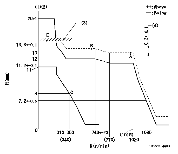
N:Pump speed
R:Rack position (mm)
(1)Target notch: K
(2)Tolerance for racks not indicated: +-0.05mm.
(3)RACK LIMIT
(4)Rack difference between N = N1 and N = N2
----------
K=14 N1=1000r/min N2=700r/min
----------
----------
K=14 N1=1000r/min N2=700r/min
----------
Speed control lever angle

F:Full speed
I:Idle
(1)Stopper bolt setting
----------
----------
a=5deg+-5deg b=28deg+-5deg
----------
----------
a=5deg+-5deg b=28deg+-5deg
Stop lever angle
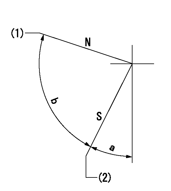
N:Pump normal
S:Stop the pump.
(1)Normal
(2)Pump speed aa and rack position bb (to be sealed at delivery)
----------
aa=0r/min bb=1-0.5mm
----------
a=37deg+-5deg b=(73deg)
----------
aa=0r/min bb=1-0.5mm
----------
a=37deg+-5deg b=(73deg)
Timing setting

(1)Pump vertical direction
(2)Coupling's key groove position at No 1 cylinder's beginning of injection
(3)-
(4)-
----------
----------
a=(40deg)
----------
----------
a=(40deg)
Information:
Start By:a. remove flywheel The crankshaft rear seal and wear sleeve come as a set and must be installed as a set. If a replacement of the seal is to be made, a replacement of the wear sleeve must also be made. 1. Make at least three holes in seal (1) with a hammer and a sharp punch.2. Use tool (A) to remove seal (1). 3. Install tool (C) in the seal bore.4. Install tool (B) between tool (C) and wear sleeve (2). Turn tool (B) until the tool makes a dent (crease) in wear sleeve (2). Do this in three or more places until the wear sleeve is loose.5. Remove tools (B) and (C), and remove wear sleeve (2) from the crankshaft.Install Crankshaft Rear Seal And Wear Sleeve
The crankshaft seal and wear sleeve come as a set and must not be separated from each other at any time. Carefully read Special Instructions, Form No. SMHS8508, that is included with each seal and wear sleeve before any handling of the seal group is made.
1. Install the rear crankshaft seal and wear sleeve with tooling (D). Use the procedures which follow: a. Clean and make a preparation of the wear sleeve inside diameter and crankshaft outside diameter with 6V1541 Quick Cure Primer. Make an application of 9S3265 Retaining Compound to the crankshaft outside diameter before the wear sleeve is installed on the crankshaft. Do not let any Quick Cure Primer or Retaining Compound get on the lip of the seal.b. Install locator (3) and the bolts on crankshaft (4).c. The seal and wear sleeve must be installed dry. Make sure the seal is installed with the part number and the arrows showing crankshaft rotation toward the outside.
The front and rear seals and wear sleeves have different spiral grooves in the seal. Because of this type of design, the rear seal group for an engine is different from the front seal group. If a seal group is installed on the wrong side of the engine, oil can actually be taken out of the engine instead of moving the oil back into the engine.
d. Put wear sleeve (2) and seal (7) as a unit in position on locator (3).e. Put installer (5) in position on locator (3).f. Put clean engine oil on the face of nut (6) and its contact area on installer (5). Install nut (6) on locator (3).g. Tighten nut (6) until installer (5) makes contact with locator (3).h. Remove tooling (D) from the crankshaft seal and wear sleeve. Tooling (D) will install the seal and wear sleeve to the correct depth on the crankshaft.End By:a. install flywheel
Have questions with 106685-4460?
Group cross 106685-4460 ZEXEL
Komatsu
Mitsubishi-Heav
Komatsu
106685-4460
9 400 617 732
6162751610
INJECTION-PUMP ASSEMBLY
SA6D170
SA6D170