Information injection-pump assembly
BOSCH
9 400 617 730
9400617730
ZEXEL
106685-4430
1066854430
MITSUBISHI-HEAV
35A6510320
35a6510320

Rating:
Cross reference number
BOSCH
9 400 617 730
9400617730
ZEXEL
106685-4430
1066854430
MITSUBISHI-HEAV
35A6510320
35a6510320
Zexel num
Bosch num
Firm num
Name
9 400 617 730
35A6510320 MITSUBISHI-HEAV
INJECTION-PUMP ASSEMBLY
S6B3-PTA * K 14CA PE6P,6PD PE
S6B3-PTA * K 14CA PE6P,6PD PE
Calibration Data:
Adjustment conditions
Test oil
1404 Test oil ISO4113 or {SAEJ967d}
1404 Test oil ISO4113 or {SAEJ967d}
Test oil temperature
degC
40
40
45
Nozzle and nozzle holder
105780-8130
Bosch type code
EFEP215A
Nozzle
105780-0050
Bosch type code
DN6TD119NP1T
Nozzle holder
105780-2090
Bosch type code
EFEP215
Opening pressure
MPa
17.2
Opening pressure
kgf/cm2
175
Injection pipe
Outer diameter - inner diameter - length (mm) mm 8-4-1000
Outer diameter - inner diameter - length (mm) mm 8-4-1000
Overflow valve
131424-3420
Overflow valve opening pressure
kPa
255
255
255
Overflow valve opening pressure
kgf/cm2
2.6
2.6
2.6
Tester oil delivery pressure
kPa
157
157
157
Tester oil delivery pressure
kgf/cm2
1.6
1.6
1.6
Direction of rotation (viewed from drive side)
Left L
Left L
Injection timing adjustment
Direction of rotation (viewed from drive side)
Left L
Left L
Injection order
1-5-3-6-
2-4
Pre-stroke
mm
2.8
2.75
2.85
Beginning of injection position
Governor side NO.1
Governor side NO.1
Difference between angles 1
Cal 1-5 deg. 60 59.5 60.5
Cal 1-5 deg. 60 59.5 60.5
Difference between angles 2
Cal 1-3 deg. 120 119.5 120.5
Cal 1-3 deg. 120 119.5 120.5
Difference between angles 3
Cal 1-6 deg. 180 179.5 180.5
Cal 1-6 deg. 180 179.5 180.5
Difference between angles 4
Cyl.1-2 deg. 240 239.5 240.5
Cyl.1-2 deg. 240 239.5 240.5
Difference between angles 5
Cal 1-4 deg. 300 299.5 300.5
Cal 1-4 deg. 300 299.5 300.5
Injection quantity adjustment
Adjusting point
A
Rack position
13.9
Pump speed
r/min
900
900
900
Average injection quantity
mm3/st.
503
494
512
Max. variation between cylinders
%
0
-3
3
Basic
*
Fixing the lever
*
Injection quantity adjustment_02
Adjusting point
C
Rack position
5.6+-0.5
Pump speed
r/min
300
300
300
Average injection quantity
mm3/st.
29.5
26.5
32.5
Max. variation between cylinders
%
0
-10
10
Fixing the rack
*
Test data Ex:
Governor adjustment
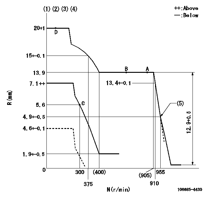
N:Pump speed
R:Rack position (mm)
(1)Maximum - minimum speed specification (using speed lever at adjustment)
(2)Target notch: K
(3)Tolerance for racks not indicated: +-0.05mm.
(4)Set the load lever's stop position so that R = aa (N = 0).
(5)Idle sub spring setting: L1.
----------
K=13 aa=4.6+-0.1mm L1=4.9-0.5mm
----------
----------
K=13 aa=4.6+-0.1mm L1=4.9-0.5mm
----------
Speed control lever angle
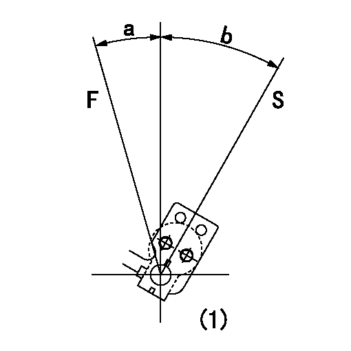
F:Full speed
S:Stop
(1)At the center of the lever key groove
----------
----------
a=15deg+-5deg b=32deg+-3deg
----------
----------
a=15deg+-5deg b=32deg+-3deg
0000000901
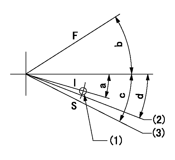
F:Full load
I:Idle
S:Stop
(1)Use the hole at R = aa
(2)Speed = bb, rack position = cc
(3)Stop side boss position
----------
aa=60mm bb=0r/min cc=4.6+-0.1mm
----------
a=8deg+-5deg b=17deg+-5deg c=34deg+-5deg d=(28deg)+-5deg
----------
aa=60mm bb=0r/min cc=4.6+-0.1mm
----------
a=8deg+-5deg b=17deg+-5deg c=34deg+-5deg d=(28deg)+-5deg
Timing setting

(1)Pump vertical direction
(2)Coupling's key groove position at No 1 cylinder's beginning of injection
(3)-
(4)-
----------
----------
a=(20deg)
----------
----------
a=(20deg)
Information:
1. Remove oil supply tube (1) and suction bell and tube (2). 2. Remove bolts (3) that hold the oil pump to the cylinder block, and remove oil pump (4). The following steps are for installation of the oil pump.3. Put oil pump (4) in position on the cylinder block. Install the bolts that hold the oil pump to the cylinder block.4. Put clean engine oil on the O-ring seals of the tubes.5. Install oil supply tube (1) and suction bell and tube (2).End By:a. install oil panDisassemble Oil Pump
Start By:a. remove oil pump1. Remove the bolt and washer that hold the gear on the shaft. 2. Use tooling (A), and remove drive gear (1) from the shaft. Remove the key from the shaft. 3. Remove retainer (3) for the bypass valve.4. Remove the spring and bypass valve.5. Remove cover (2) from the pump body. 6. Use tooling (B), and remove the bearings from the cover. 7. Remove gears (5) and (6) from pump body (4).8. Use tooling (B), and remove the bearings from pump body (4).Assemble Oil Pump
1. Use tooling (B) to install the bearings in the pump body. Install the bearings so the joint in the bearings is 30° 15° from the center line of the oil pump outlet passage (7). 2. Install idler gear (5) and drive gear (6) in the oil pump body. Put clean engine oil on the bearings and the gears. 3. Use tooling (B), and install the bearings in cover (2). Install the bearings so the joint in the bearings is 30° 15° from the center line of the bearing bores toward oil pump outlet passage (7).4. Install bypass valve (8), spring (9) and the retainer.5. Install the key on the shaft. 6. Install gear (1) on the shaft. Install the washer and bolt that hold the gear on the shaft. Be sure the pump turns freely after assembly.End By:a. install oil pump