Information injection-pump assembly
ZEXEL
106685-4400
1066854400

Rating:
Cross reference number
ZEXEL
106685-4400
1066854400
Zexel num
Bosch num
Firm num
Name
106685-4400
INJECTION-PUMP ASSEMBLY
Calibration Data:
Adjustment conditions
Test oil
1404 Test oil ISO4113 or {SAEJ967d}
1404 Test oil ISO4113 or {SAEJ967d}
Test oil temperature
degC
40
40
45
Nozzle and nozzle holder
105780-8130
Bosch type code
EFEP215A
Nozzle
105780-0050
Bosch type code
DN6TD119NP1T
Nozzle holder
105780-2090
Bosch type code
EFEP215
Opening pressure
MPa
17.2
Opening pressure
kgf/cm2
175
Injection pipe
Outer diameter - inner diameter - length (mm) mm 8-4-1000
Outer diameter - inner diameter - length (mm) mm 8-4-1000
Overflow valve
131425-1620
Overflow valve opening pressure
kPa
255
221
289
Overflow valve opening pressure
kgf/cm2
2.6
2.25
2.95
Tester oil delivery pressure
kPa
255
255
255
Tester oil delivery pressure
kgf/cm2
2.6
2.6
2.6
Direction of rotation (viewed from drive side)
Right R
Right R
Injection timing adjustment
Direction of rotation (viewed from drive side)
Right R
Right R
Injection order
1-5-3-6-
2-4
Pre-stroke
mm
3
2.95
3.05
Beginning of injection position
Drive side NO.1
Drive side NO.1
Difference between angles 1
Cal 1-5 deg. 60 59.5 60.5
Cal 1-5 deg. 60 59.5 60.5
Difference between angles 2
Cal 1-3 deg. 120 119.5 120.5
Cal 1-3 deg. 120 119.5 120.5
Difference between angles 3
Cal 1-6 deg. 180 179.5 180.5
Cal 1-6 deg. 180 179.5 180.5
Difference between angles 4
Cyl.1-2 deg. 240 239.5 240.5
Cyl.1-2 deg. 240 239.5 240.5
Difference between angles 5
Cal 1-4 deg. 300 299.5 300.5
Cal 1-4 deg. 300 299.5 300.5
Injection quantity adjustment
Adjusting point
A
Rack position
13.8
Pump speed
r/min
900
900
900
Average injection quantity
mm3/st.
409
404
414
Max. variation between cylinders
%
0
-3
3
Basic
*
Fixing the rack
*
Remarks
Standard point A's rack position same as row R
Standard point A's rack position same as row R
Injection quantity adjustment_02
Adjusting point
C
Rack position
7.2+-0.5
Pump speed
r/min
400
400
400
Average injection quantity
mm3/st.
20
18.5
21.5
Max. variation between cylinders
%
0
-15
15
Fixing the rack
*
Test data Ex:
Governor adjustment
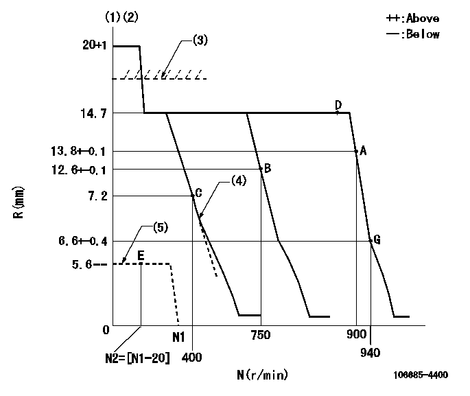
N:Pump speed
R:Rack position (mm)
(1)Target notch: K
(2)Tolerance for racks not indicated: +-0.05mm.
(3)RACK LIMIT for 106684-4253
(4)Idle sub spring setting: L1.
(5)Stop lever at stopping (with the speed lever at full)
----------
K=22 L1=7.2-0.5mm
----------
----------
K=22 L1=7.2-0.5mm
----------
Speed control lever angle
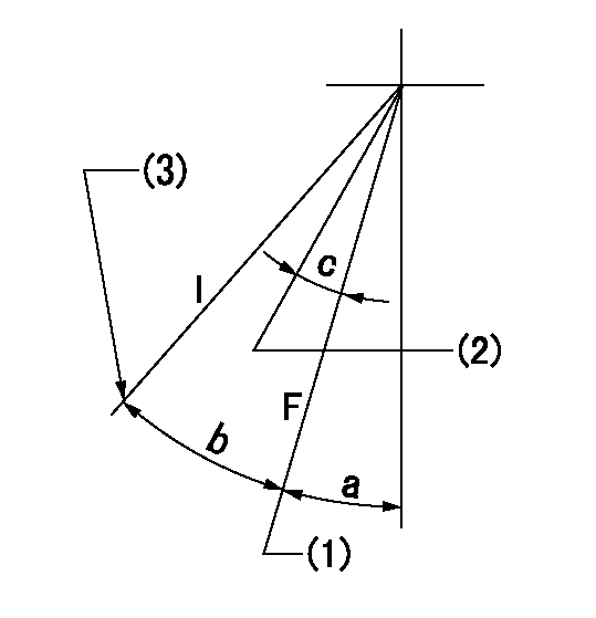
F:Full speed
I:Idle
(1)Set the pump speed at aa. ( At delivery )
(2)Set the pump speed at bb.
(3)Stopper bolt setting
----------
aa=900r/min bb=750r/min
----------
a=8deg+-5deg b=29deg+-5deg c=10deg+-5deg
----------
aa=900r/min bb=750r/min
----------
a=8deg+-5deg b=29deg+-5deg c=10deg+-5deg
Stop lever angle
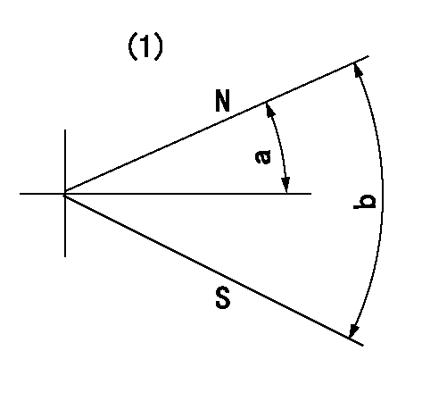
N:Pump normal
S:Stop the pump.
(1)No return spring
----------
----------
a=26.5deg+-5deg b=53deg+-5deg
----------
----------
a=26.5deg+-5deg b=53deg+-5deg
Timing setting

(1)Pump vertical direction
(2)Coupling's key groove position at No 1 cylinder's beginning of injection
(3)B.T.D.C.: aa
(4)-
----------
aa=20deg
----------
a=(30deg)
----------
aa=20deg
----------
a=(30deg)
Information:
3. Loosen the clamps on breather tube (1), and pull it back for clearance. Loosen the clamps on hose (3). Slide hose (3) off of the water pump cover.4. Remove two bolts and remove elbow (2). 5. Remove bolt (4) from the cover on the side of the cylinder block. 6. Remove the three bolts that hold cover (5) to the water pump. Remove cover (5) from the water pump. 7. Remove the two bolts, and remove elbow (7) from bonnet (6). Remove the two bolts, and remove bonnet (6) from the water pump. It is not necessary to remove bolts (10). These bolts only hold the cover to the timing gear cover.8. Remove six long bolts (9) that hold the water pump to the timing gear cover. Remove water pump (8). The following steps are for the installation of the water pump.9. Check the O-ring seals and gaskets, and make replacements if needed. 10. Make sure O-ring seal (11) is in position on the water pump. Put water pump (8) into position in the timing gear cover. Install the bolts that hold the water pump in place.11. Make sure the gaskets are in place. Connect bonnet (6) to the water pump. Connect elbow (7) to the bonnet. 12. Make sure O-ring seal (12) is in position, and install cover (5) on the water pump.13. Install bolt (4) on the cover on the side of the engine.14. Put breather tube (1) in position, and install the clamps that hold it.15. Install the alternator mounting group and alternator on the engine if so equipped. 16. Install the gasket and O-ring seal on elbow (2). Lubricate the O-ring seal with clean oil. Install elbow (2)in the bore of the water pump. Use two bolts to fasten the elbow to the cylinder head.17. Slide hose (3) into position on the water pump. Tighten the hose clamp.18. Fill the cooling system to the correct level. See the Maintenance Manual.Disassemble And Assemble Water Pump
Start By:a. remove water pump The water pump seal can be replaced without removing the water pump from the engine.An intermittent leakage of a small amount of coolant from the hole in the water pump housing is not an indication of a water pump seal failure. This is required to provide lubrication for the seal. Replace the water pump seal only if a large amount of leakage or a constant flow of coolant is observed draining from the water pump housing. 1. Remove O-ring seal (3) from adapter (4). Remove the adapter from housing (7). Remove the O-ring seal from the outside of the adapter.2. Remove bolt (1) and washer (2). Use tooling (A) to remove impeller (6) from shaft (13).3. Remove spring and seal (5) from the shaft.4. Remove four bolts (16) from retainer (12) that hold the shaft assembly to the pump housing. Remove O-ring seal (18) from housing (7).5. Remove gear and shaft assembly (17) from the housing. Remove bolt (15), retainer (14), and retainer (12) from
Start By:a. remove water pump The water pump seal can be replaced without removing the water pump from the engine.An intermittent leakage of a small amount of coolant from the hole in the water pump housing is not an indication of a water pump seal failure. This is required to provide lubrication for the seal. Replace the water pump seal only if a large amount of leakage or a constant flow of coolant is observed draining from the water pump housing. 1. Remove O-ring seal (3) from adapter (4). Remove the adapter from housing (7). Remove the O-ring seal from the outside of the adapter.2. Remove bolt (1) and washer (2). Use tooling (A) to remove impeller (6) from shaft (13).3. Remove spring and seal (5) from the shaft.4. Remove four bolts (16) from retainer (12) that hold the shaft assembly to the pump housing. Remove O-ring seal (18) from housing (7).5. Remove gear and shaft assembly (17) from the housing. Remove bolt (15), retainer (14), and retainer (12) from
Have questions with 106685-4400?
Group cross 106685-4400 ZEXEL
106685-4400
INJECTION-PUMP ASSEMBLY