Information injection-pump assembly
BOSCH
9 400 611 908
9400611908
ZEXEL
106685-4250
1066854250

Rating:
Service parts 106685-4250 INJECTION-PUMP ASSEMBLY:
1.
_
5.
AUTOM. ADVANCE MECHANIS
8.
_
9.
_
11.
Nozzle and Holder
6152-15-3600
12.
Open Pre:MPa(Kqf/cm2)
26.0{265}
15.
NOZZLE SET
Include in #1:
106685-4250
as INJECTION-PUMP ASSEMBLY
Cross reference number
BOSCH
9 400 611 908
9400611908
ZEXEL
106685-4250
1066854250
Zexel num
Bosch num
Firm num
Name
Calibration Data:
Adjustment conditions
Test oil
1404 Test oil ISO4113 or {SAEJ967d}
1404 Test oil ISO4113 or {SAEJ967d}
Test oil temperature
degC
40
40
45
Nozzle and nozzle holder
105780-8130
Bosch type code
EFEP215A
Nozzle
105780-0050
Bosch type code
DN6TD119NP1T
Nozzle holder
105780-2090
Bosch type code
EFEP215
Opening pressure
MPa
17.2
Opening pressure
kgf/cm2
175
Injection pipe
Outer diameter - inner diameter - length (mm) mm 8-4-1000
Outer diameter - inner diameter - length (mm) mm 8-4-1000
Overflow valve
131425-2120
Overflow valve opening pressure
kPa
157
123
191
Overflow valve opening pressure
kgf/cm2
1.6
1.25
1.95
Tester oil delivery pressure
kPa
157
157
157
Tester oil delivery pressure
kgf/cm2
1.6
1.6
1.6
Direction of rotation (viewed from drive side)
Left L
Left L
Injection timing adjustment
Direction of rotation (viewed from drive side)
Left L
Left L
Injection order
1-5-3-6-
2-4
Pre-stroke
mm
3.3
3.25
3.35
Rack position
R=10++
Beginning of injection position
Drive side NO.1
Drive side NO.1
Difference between angles 1
Cal 1-5 deg. 60 59.5 60.5
Cal 1-5 deg. 60 59.5 60.5
Difference between angles 2
Cal 1-3 deg. 120 119.5 120.5
Cal 1-3 deg. 120 119.5 120.5
Difference between angles 3
Cal 1-6 deg. 180 179.5 180.5
Cal 1-6 deg. 180 179.5 180.5
Difference between angles 4
Cyl.1-2 deg. 240 239.5 240.5
Cyl.1-2 deg. 240 239.5 240.5
Difference between angles 5
Cal 1-4 deg. 300 299.5 300.5
Cal 1-4 deg. 300 299.5 300.5
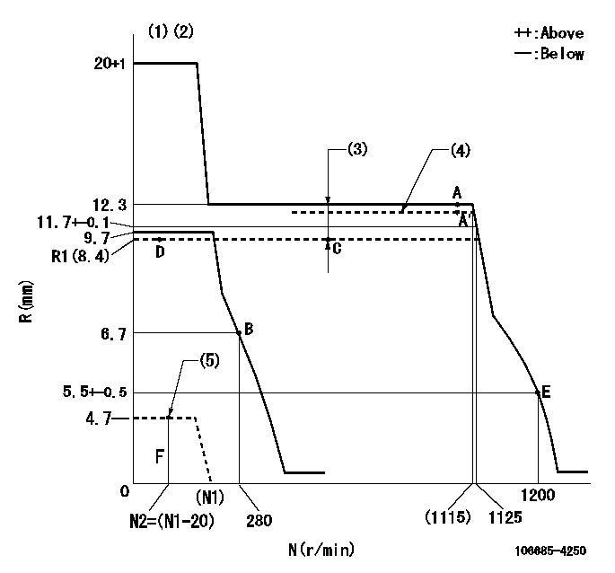
Injection quantity adjustment
Adjusting point
A
Rack position
12.3
Pump speed
r/min
1100
1100
1100
Average injection quantity
mm3/st.
404
399
409
Max. variation between cylinders
%
0
-3
3
Basic
*
Fixing the lever
*
Boost pressure
kPa
131
131
Boost pressure
mmHg
980
980
Injection quantity adjustment_02
Adjusting point
B
Rack position
6.7+-0.5
Pump speed
r/min
280
280
280
Average injection quantity
mm3/st.
28.5
26.5
30.5
Max. variation between cylinders
%
0
-15
15
Fixing the rack
*
Boost pressure
kPa
0
0
0
Boost pressure
mmHg
0
0
0
Injection quantity adjustment_03
Adjusting point
C
Rack position
R1(8.4)
Pump speed
r/min
600
600
600
Average injection quantity
mm3/st.
185.5
182.5
188.5
Fixing the lever
*
Boost pressure
kPa
0
0
0
Boost pressure
mmHg
0
0
0
Boost compensator adjustment
Pump speed
r/min
600
600
600
Rack position
R1(8.4)
Boost pressure
kPa
30.7
28
33.4
Boost pressure
mmHg
230
210
250
Boost compensator adjustment_02
Pump speed
r/min
600
600
600
Rack position
R1+3.9
Boost pressure
kPa
117
110.3
123.7
Boost pressure
mmHg
880
830
930
Test data Ex:
Governor adjustment
N:Pump speed
R:Rack position (mm)
(1)Target notch: K
(2)Tolerance for racks not indicated: +-0.05mm.
(3)Boost compensator stroke: BCL
(4)Set using full load screw at shipping.
(5)Stop lever at stopping (with the speed lever at full)
----------
K=13 BCL=3.9+-0.1mm
----------
----------
K=13 BCL=3.9+-0.1mm
----------
Speed control lever angle
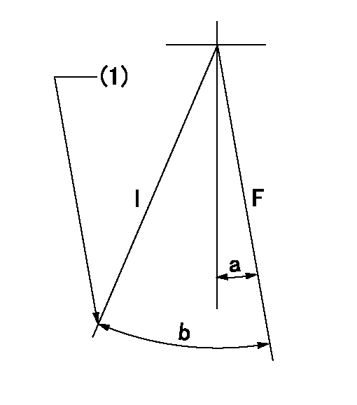
F:Full speed
I:Idle
(1)Stopper bolt setting
----------
----------
a=2deg+-5deg b=34deg+-5deg
----------
----------
a=2deg+-5deg b=34deg+-5deg
Stop lever angle
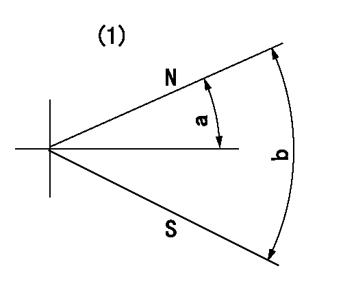
N:Pump normal
S:Stop the pump.
(1)No return spring
----------
----------
a=19deg+-5deg b=53deg+-5deg
----------
----------
a=19deg+-5deg b=53deg+-5deg
Timing setting

(1)Pump vertical direction
(2)Coupling's key groove position at No 1 cylinder's beginning of injection
(3)B.T.D.C.: aa
(4)At rack position = bb or more
----------
aa=25deg bb=10mm
----------
a=(150deg)
----------
aa=25deg bb=10mm
----------
a=(150deg)
Information:
Install the new 291-5165 Bellows (10) to tube assembly (2) by placing the end of the bellows with the liner on the flange of the tube assembly. Secure bellows (10) to tube assembly (2) by using one new 202-1838 V Band Clamp (11). Refer to Illustration 7.
Illustration 8 g01794917
(12) 313-9428 Tube As
Install the flanged end of the new 313-9428 Tube As (12) to bellows (10) by using one new V-band clamp (11). Refer to Illustration 8.Note: Make sure that the tube assembly is temporarily supported so that the tube assembly axis lines up with the axis of the bellows before securing the tube assembly to the bellows. That way the weight of the tube is on the support and not on the bellows.
Illustration 9 g01794933
(13) 294-9631 Clamp As (14) 310-7675 Bracket (15) 5P-1076 Hard Washer (16) 8T-4183 Bolt
Install the bottom half of the new 294-9631 Clamp As (13) to the two new 310-7675 Brackets (14) by using two new 5P-1076