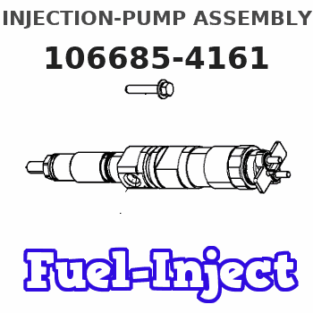
Information injection-pump assembly
BOSCH
9 400 612 283
9400612283
ZEXEL
106685-4161
1066854161
Rating:
Service parts 106685-4161 INJECTION-PUMP ASSEMBLY:
1.
_
5.
AUTOM. ADVANCE MECHANIS
7.
COUPLING PLATE
8.
_
9.
_
11.
Nozzle and Holder
6212-11-7100
12.
Open Pre:MPa(Kqf/cm2)
24.5{250}
15.
NOZZLE SET
Include in #1:
106685-4161
as INJECTION-PUMP ASSEMBLY
Cross reference number
BOSCH
9 400 612 283
9400612283
ZEXEL
106685-4161
1066854161
Zexel num
Bosch num
Firm num
Name
Calibration Data:
Adjustment conditions
Test oil
1404 Test oil ISO4113 or {SAEJ967d}
1404 Test oil ISO4113 or {SAEJ967d}
Test oil temperature
degC
40
40
45
Nozzle and nozzle holder
105780-8130
Bosch type code
EFEP215A
Nozzle
105780-0050
Bosch type code
DN6TD119NP1T
Nozzle holder
105780-2090
Bosch type code
EFEP215
Opening pressure
MPa
17.2
Opening pressure
kgf/cm2
175
Injection pipe
Outer diameter - inner diameter - length (mm) mm 8-4-1000
Outer diameter - inner diameter - length (mm) mm 8-4-1000
Overflow valve
131425-1620
Overflow valve opening pressure
kPa
255
221
289
Overflow valve opening pressure
kgf/cm2
2.6
2.25
2.95
Tester oil delivery pressure
kPa
255
255
255
Tester oil delivery pressure
kgf/cm2
2.6
2.6
2.6
RED3 control unit part number
407910-3
960
RED3 rack sensor specifications
mm
19
Direction of rotation (viewed from drive side)
Right R
Right R
Injection timing adjustment
Direction of rotation (viewed from drive side)
Right R
Right R
Injection order
1-5-3-6-
2-4
Pre-stroke
mm
3.1
3.05
3.15
Beginning of injection position
Drive side NO.1
Drive side NO.1
Difference between angles 1
Cal 1-5 deg. 60 59.5 60.5
Cal 1-5 deg. 60 59.5 60.5
Difference between angles 2
Cal 1-3 deg. 120 119.5 120.5
Cal 1-3 deg. 120 119.5 120.5
Difference between angles 3
Cal 1-6 deg. 180 179.5 180.5
Cal 1-6 deg. 180 179.5 180.5
Difference between angles 4
Cyl.1-2 deg. 240 239.5 240.5
Cyl.1-2 deg. 240 239.5 240.5
Difference between angles 5
Cal 1-4 deg. 300 299.5 300.5
Cal 1-4 deg. 300 299.5 300.5
Injection quantity adjustment
Rack position
(15.5)
Vist
V
1.53
1.53
1.53
Pump speed
r/min
900
900
900
Average injection quantity
mm3/st.
497
492
502
Max. variation between cylinders
%
0
-3
3
Basic
*
Injection quantity adjustment_02
Rack position
(5.7)
Vist
V
3
2.9
3.1
Pump speed
r/min
400
400
400
Average injection quantity
mm3/st.
9
7.5
10.5
Max. variation between cylinders
%
0
-15
15
Test data Ex:
Speed control lever angle

N:Pump normal
S:Stop the pump.
(1)Rack position = aa
(2)Rack position bb
----------
aa=20mm bb=1mm
----------
a=27deg+-5deg b=37deg+-5deg
----------
aa=20mm bb=1mm
----------
a=27deg+-5deg b=37deg+-5deg
0000000901
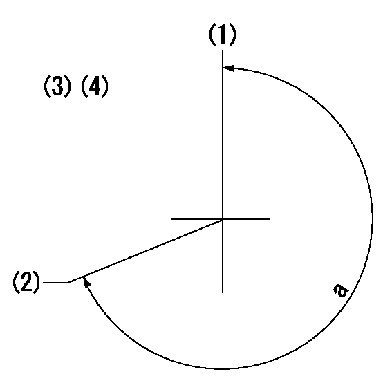
(1)Pump vertical direction
(2)Coupling's key groove position at No 1 cylinder's beginning of injection
(3)-
(4)-
----------
----------
a=(260deg)
----------
----------
a=(260deg)
Stop lever angle

(Rs) rack sensor specifications
(C/U) control unit part number
(V) Rack sensor output voltage
(R) Rack position (mm)
1. Confirming governor output characteristics (rack 19 mm, span 6 mm)
(1)When the output voltages of the rack sensor are V1 and V2, check that the rack positions R1 and R2 in the table above are satisfied.
----------
----------
----------
----------
Information:
Model Views
The sample model view drawings show various typical Caterpillar 3408C and 3412C Engine features. The drawings are generic and do not reflect all available options. Because of individual applications, your engine may appear different from those illustrated.
3408 Model Views:(1) Exhaust(2) Oil Level Gauge (Dipstick)(3) Crankcase Breather(4) Oil Filler Cap(5) Manual Shutoff Shaft(6) Lifting Eye(7) Fuel Priming Pump(8) Fuel Pressure Gauge(9) Fuel Filter(10) Oil Filter(11) Supplemental Coolant Additive Element(12) Oil Drain(13) Air Inlet(14) Turbocharger(15) and Magnetic Pickup Location.
3412 Model Views:(1) Exhaust(2) Oil Level Gauge (Dipstick)(3) Crankcase Breather(4) Oil Filler Cap(5) Manual Shutoff Shaft(6) Lifting Eye(7) Fuel Priming Pump(8) Fuel Pressure Gauge(9) Fuel Filter(10) Oil Filter(11) Supplemental Coolant Additive Element(12) Oil Drain(13) Air Inlet(14) Turbocharger(15) Magnetic Pickup LocationEngine Information
Engine Descriptions
The engines described in this publication are the 3408C and 3412C Industrial Diesel Engines. They are designed primarily for agricultural, petroleum, and auxiliary applications.A mechanical governor controls the fuel injection pump output, maintaining the engine rpm selected by the operator. Individual injection pumps (one for each cylinder) meter and pump fuel under high pressure to injection nozzles. Automatic timing advance provides the best fuel injection timing over the full range of engine speed.The fuel ratio control is located on the governor. The fuel ratio control restricts the fuel rack movement. Only the proper amount of fuel is allowed to be injected into the cylinders during acceleration. This minimizes exhaust smoke.Inlet air is filtered by an air cleaner. The air is compressed by a turbocharger before the air enters the engine cylinders. The turbocharger is driven by engine exhaust. The engines can be turbocharged, or turbocharged with jacket water aftercooling.The engines are four cycle engines. Each cylinder head has two inlet valves and two exhaust valves. The rocker arms and the valves are actuated by the camshaft. The action is performed by mechanical lifters and push rods.The cooling system consists of:* two thermostats (one for each bank) to regulate water temperature.* a gear driven centrifugal pump.* an oil cooler, and* a radiator (incorporating a shunt system).The engine lubricating oil, which is both cooled and filtered, is supplied by a gear-type pump. Bypass valves provide unrestricted flow of lubrication oil to the engine parts if oil viscosity is high, or if the oil cooler or the oil filter elements become plugged.Engine efficiency, efficiency of emission controls, and engine performance depend on adherence to proper operation and maintenance recommendations. Engine performance and efficiency also depend on the use of recommended coolant/antifreeze, fuels, and lubrication oils. Follow the recommended Maintenance Schedule found in this publication, paying attention to emission related components, air cleaner, oil, oil filter, fuel and fuel filter maintenance.