Information injection-pump assembly
BOSCH
9 400 611 284
9400611284
ZEXEL
106685-4130
1066854130
Rating:
Service parts 106685-4130 INJECTION-PUMP ASSEMBLY:
1.
_
5.
AUTOM. ADVANCE MECHANIS
7.
COUPLING PLATE
8.
_
9.
_
11.
Nozzle and Holder
6212-12-3300
12.
Open Pre:MPa(Kqf/cm2)
24.5{250}
15.
NOZZLE SET
Include in #1:
106685-4130
as INJECTION-PUMP ASSEMBLY
Cross reference number
BOSCH
9 400 611 284
9400611284
ZEXEL
106685-4130
1066854130
Zexel num
Bosch num
Firm num
Name
Calibration Data:
Adjustment conditions
Test oil
1404 Test oil ISO4113 or {SAEJ967d}
1404 Test oil ISO4113 or {SAEJ967d}
Test oil temperature
degC
40
40
45
Nozzle and nozzle holder
105780-8130
Bosch type code
EFEP215A
Nozzle
105780-0050
Bosch type code
DN6TD119NP1T
Nozzle holder
105780-2090
Bosch type code
EFEP215
Opening pressure
MPa
17.2
Opening pressure
kgf/cm2
175
Injection pipe
Outer diameter - inner diameter - length (mm) mm 8-4-1000
Outer diameter - inner diameter - length (mm) mm 8-4-1000
Overflow valve
131425-1620
Overflow valve opening pressure
kPa
255
221
289
Overflow valve opening pressure
kgf/cm2
2.6
2.25
2.95
Tester oil delivery pressure
kPa
157
157
157
Tester oil delivery pressure
kgf/cm2
1.6
1.6
1.6
Direction of rotation (viewed from drive side)
Right R
Right R
Injection timing adjustment
Direction of rotation (viewed from drive side)
Right R
Right R
Injection order
1-5-3-6-
2-4
Pre-stroke
mm
3.3
3.25
3.35
Beginning of injection position
Drive side NO.1
Drive side NO.1
Difference between angles 1
Cal 1-5 deg. 60 59.5 60.5
Cal 1-5 deg. 60 59.5 60.5
Difference between angles 2
Cal 1-3 deg. 120 119.5 120.5
Cal 1-3 deg. 120 119.5 120.5
Difference between angles 3
Cal 1-6 deg. 180 179.5 180.5
Cal 1-6 deg. 180 179.5 180.5
Difference between angles 4
Cyl.1-2 deg. 240 239.5 240.5
Cyl.1-2 deg. 240 239.5 240.5
Difference between angles 5
Cal 1-4 deg. 300 299.5 300.5
Cal 1-4 deg. 300 299.5 300.5
Injection quantity adjustment
Adjusting point
A
Rack position
12.7
Pump speed
r/min
900
900
900
Average injection quantity
mm3/st.
348
343
353
Max. variation between cylinders
%
0
-3
3
Basic
*
Fixing the rack
*
Injection quantity adjustment_02
Adjusting point
B
Rack position
12.2
Pump speed
r/min
750
750
750
Average injection quantity
mm3/st.
304
298
310
Fixing the rack
*
Injection quantity adjustment_03
Adjusting point
C
Rack position
6.8+-0.5
Pump speed
r/min
405
405
405
Average injection quantity
mm3/st.
8.5
7
10
Max. variation between cylinders
%
0
-15
15
Fixing the rack
*
Injection quantity adjustment_04
Adjusting point
E
Rack position
-
Pump speed
r/min
100
100
100
Average injection quantity
mm3/st.
405
395
415
Fixing the lever
*
Rack limit
*
Test data Ex:
Governor adjustment
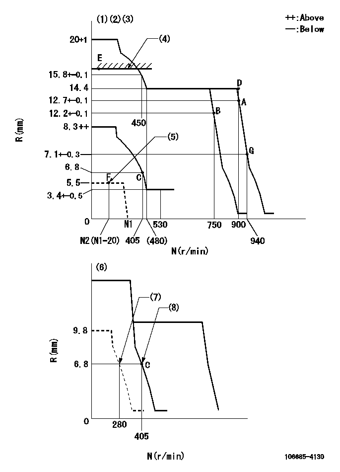
N:Pump speed
R:Rack position (mm)
(1)Minimum - maximum speed specification
(2)Target notch: K
(3)Tolerance for racks not indicated: +-0.05mm.
(4)RACK LIMIT
(5)Load lever stop (with the speed lever at full)
(6)Variable speed specification: idling adjustment
(7)Set idle sub-spring
(8)Main spring setting
----------
K=18
----------
----------
K=18
----------
Speed control lever angle
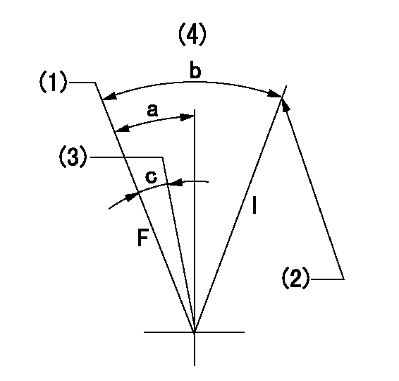
F:Full speed
I:Idle
(1)Set the pump speed at aa
(2)Stopper bolt setting
(3)Set the pump speed at bb.
(4)Base lever only
----------
aa=900r/min bb=750r/min
----------
a=19deg+-5deg b=28deg+-5deg c=10deg+-5deg
----------
aa=900r/min bb=750r/min
----------
a=19deg+-5deg b=28deg+-5deg c=10deg+-5deg
0000000901
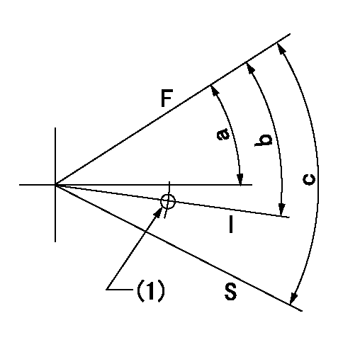
F:Full load
I:Idle
S:Stop
(1)Use the hole at R = aa
----------
aa=27mm
----------
a=26.5deg+-5deg b=29deg+-5deg c=53deg+-5deg
----------
aa=27mm
----------
a=26.5deg+-5deg b=29deg+-5deg c=53deg+-5deg
Timing setting

(1)Pump vertical direction
(2)Coupling's key groove position at No 1 cylinder's beginning of injection
(3)-
(4)-
----------
----------
a=(10deg)
----------
----------
a=(10deg)
Information:
Inspect/Replace
Alternator and Fan Drive Belts
Inspect the condition and adjustment of alternator and accessory drive belts. Examine all drive belts for wear and replace if they show any signs of wear. Loose or worn pulley grooves cause belt slippage and low accessory drive speed. If belts are too loose, they vibrate enough to cause unnecessary wear on the belts and pulleys and possibly slip enough to cause overheating.If belts are too tight, unnecessary stresses are placed upon the pulley bearings and belts which might shorten the life of both.If one belt in a set requires replacement, always install a new matched set of belts. Never replace just the worn belt. If only the worn belt is replaced, the new belt will carry all the load, as it will not be stretched as much as the older belts. All the belts will fail in rapid succession.Adjust
1. Remove belt guard. Inspect the condition and adjustment of alternator belts and accessory drive belts, if equipped.2. To check the belt tension, apply 110 Newton (25 lb) force, perpendicular to the belt, midway between the driving and driven pulley. Measure the belt deflection. Correctly adjusted belts will deflect 15 to 20 mm (9/16 to 7/8 inch).If the belt does not require replacement or adjustment, install the belt guard. If the belt requires adjustment or replacement, do not install the belt guard. Perform the following procedure to adjust the belt tension.
(1) Typical belt assembly mounting bolt(2) adjusting nut3. Loosen the mounting bolt (1).4. Loosen the bracket adjusting nut(s) (2).5. Tighten or loosen the bracket adjusting nut(s) to obtain the correct adjustment.6. Tighten nuts (1) and (2).7. Check the belt tension. If the belt tension requires further adjustment, repeat steps 3 through 6.8. Install the belt guard.If new belts are installed, check the belt adjustment again after 30 minutes of engine operation.Hoses and Clamps
* Inspect all hoses for leaks due to cracking, softness and loose clamps. Replace hoses that are cracked or soft and tighten loose clamps.
Do not bend or strike high pressure lines. Do not install bent or damaged lines, tubes or hoses. Repair any loose or damaged fuel and oil lines, tubes and hoses. Leaks can cause fires. Inspect all lines, tubes and hoses carefully. Tighten all connections to the recommended torque.
Check for the following:* End fittings damaged, leaking or displaced.* Outer covering chafed or cut and wire reinforcing exposed.* Outer covering ballooning locally.* Evidence of kinking or crushing of the flexible part of the hose.* Armoring embedded in the outer cover.A constant torque hose clamp can be used in place of any standard hose clamp. Make sure the constant torque hose clamp is the same size as the standard clamp. Due to extreme temperature changes, hose will heat set. Heat setting causes hose clamps to loosen. Loose hose clamps can result in leaks. There have been reports of component failures caused by hose clamps loosening. The new, constant torque hose clamp will help prevent these failures.Each installation application can be different depending on