Information injection-pump assembly
BOSCH
9 400 611 907
9400611907
ZEXEL
106685-4120
1066854120

Rating:
Service parts 106685-4120 INJECTION-PUMP ASSEMBLY:
1.
_
5.
AUTOM. ADVANCE MECHANIS
8.
_
9.
_
11.
Nozzle and Holder
6212-16-3400
12.
Open Pre:MPa(Kqf/cm2)
27.0{275}
15.
NOZZLE SET
Include in #1:
106685-4120
as INJECTION-PUMP ASSEMBLY
Cross reference number
BOSCH
9 400 611 907
9400611907
ZEXEL
106685-4120
1066854120
Zexel num
Bosch num
Firm num
Name
Calibration Data:
Adjustment conditions
Test oil
1404 Test oil ISO4113 or {SAEJ967d}
1404 Test oil ISO4113 or {SAEJ967d}
Test oil temperature
degC
40
40
45
Nozzle and nozzle holder
105780-8130
Bosch type code
EFEP215A
Nozzle
105780-0050
Bosch type code
DN6TD119NP1T
Nozzle holder
105780-2090
Bosch type code
EFEP215
Opening pressure
MPa
17.2
Opening pressure
kgf/cm2
175
Injection pipe
Outer diameter - inner diameter - length (mm) mm 8-4-1000
Outer diameter - inner diameter - length (mm) mm 8-4-1000
Overflow valve
131425-1620
Overflow valve opening pressure
kPa
255
255
255
Overflow valve opening pressure
kgf/cm2
2.6
2.6
2.6
Tester oil delivery pressure
kPa
157
157
157
Tester oil delivery pressure
kgf/cm2
1.6
1.6
1.6
Direction of rotation (viewed from drive side)
Right R
Right R
Injection timing adjustment
Direction of rotation (viewed from drive side)
Right R
Right R
Injection order
1-5-3-6-
2-4
Pre-stroke
mm
3.5
3.45
3.55
Beginning of injection position
Drive side NO.1
Drive side NO.1
Difference between angles 1
Cal 1-5 deg. 60 59.5 60.5
Cal 1-5 deg. 60 59.5 60.5
Difference between angles 2
Cal 1-3 deg. 120 119.5 120.5
Cal 1-3 deg. 120 119.5 120.5
Difference between angles 3
Cal 1-6 deg. 180 179.5 180.5
Cal 1-6 deg. 180 179.5 180.5
Difference between angles 4
Cyl.1-2 deg. 240 239.5 240.5
Cyl.1-2 deg. 240 239.5 240.5
Difference between angles 5
Cal 1-4 deg. 300 299.5 300.5
Cal 1-4 deg. 300 299.5 300.5
Injection quantity adjustment
Adjusting point
A
Rack position
14.8
Pump speed
r/min
1100
1100
1100
Average injection quantity
mm3/st.
442
437
447
Max. variation between cylinders
%
0
-3
3
Basic
*
Fixing the lever
*
Boost pressure
kPa
131
131
Boost pressure
mmHg
980
980
Injection quantity adjustment_02
Adjusting point
B
Rack position
8.6+-0.5
Pump speed
r/min
275
275
275
Average injection quantity
mm3/st.
8.5
6.5
10.5
Max. variation between cylinders
%
0
-15
15
Fixing the rack
*
Boost pressure
kPa
0
0
0
Boost pressure
mmHg
0
0
0
Boost compensator adjustment
Pump speed
r/min
600
600
600
Rack position
R1-3.9
Boost pressure
kPa
30.7
28
33.4
Boost pressure
mmHg
230
210
250
Boost compensator adjustment_02
Pump speed
r/min
600
600
600
Rack position
R1(14.8)
Boost pressure
kPa
117
117
117
Boost pressure
mmHg
880
880
880
Test data Ex:
Governor adjustment
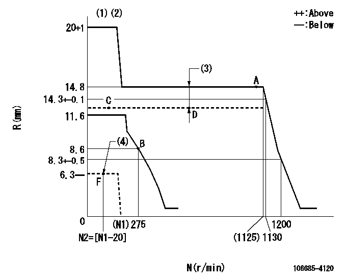
N:Pump speed
R:Rack position (mm)
(1)Target notch: K
(2)Tolerance for racks not indicated: +-0.05mm.
(3)Boost compensator stroke: BCL
(4)Stop lever at stopping (with the speed lever at full)
----------
K=14 BCL=3.9+-0.1mm
----------
----------
K=14 BCL=3.9+-0.1mm
----------
Speed control lever angle
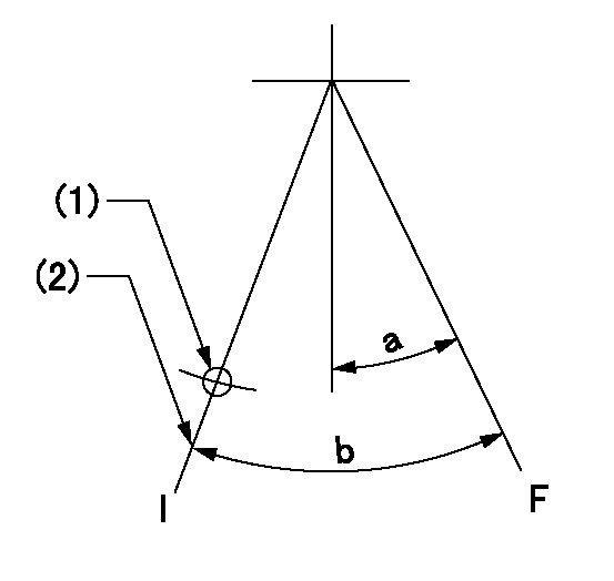
F:Full speed
I:Idle
(1)Use the hole at R = aa
(2)Stopper bolt setting
----------
aa=90mm
----------
a=(7deg)+-5deg b=(38deg)+-5deg
----------
aa=90mm
----------
a=(7deg)+-5deg b=(38deg)+-5deg
Stop lever angle
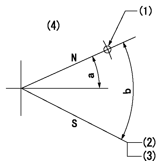
N:Pump normal
S:Stop the pump.
(1)Use the hole at R = aa
(2)Rack position = bb or less
(3)At speed = cc.
(4)No return spring
----------
aa=28mm bb=6.3mm cc=(N1-20)mm
----------
a=19deg+-5deg b=53deg+-5deg
----------
aa=28mm bb=6.3mm cc=(N1-20)mm
----------
a=19deg+-5deg b=53deg+-5deg
Timing setting
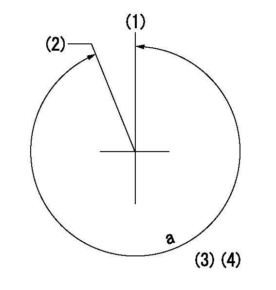
(1)Pump vertical direction
(2)Coupling's key groove position at No 1 cylinder's beginning of injection
(3)-
(4)-
----------
----------
a=(350deg)
----------
----------
a=(350deg)
Information:
Caterpillar's Scheduled Oil Sampling (S*O*S) analysis is the best indicator for determining what is happening inside your engine.S*O*S analysis is a diagnostic tool used to determine oil performance and component wear rates. S*O*S analysis uses a series of tests designed to identify and measure contamination such as:* soot, sulfur, etc.* degradation such as the presence of fuel, water and antifreeze in a sample of oil.* the amount of wear metals present in the oil sample.Wear metal present in the oil sample are compared to established Caterpillar norms to determine acceptability. S*O*S analysis must be performed on a continuing basis to be effective as an indicator. Intermittent sampling does not allow wear rate trend lines to be established.Obtain S*O*S samples at regularly scheduled intervals to monitor the condition and maintenance requirement of your engine. Each oil sample should be taken when the oil is warm and well mixed to ensure that the sample is representative of the oil in the engine crankcase.Consult your Caterpillar dealer for complete information and assistance in establishing an S*O*S analysis program for your engine(s).S*O*S Analysis
S*O*S analysis is composed of three basic tests:* Wear analysis* Chemical and Physical Tests* Oil Condition Analysis Wear analysis is performed with an atomic absorption spectrophotometer to monitor component wear by identifying and measuring concentrations, in parts per million, of wear elements present in the oil. Based on known normal concentrations data, maximum limits of wear elements are established. Impending failures can be identified when test results deviate form concentration levels established as acceptable, based on normal wear. Chemical and Physical Tests detect the presence of water, fuel and glycol (antifreeze) in the oil and determine whether or not their concentrations exceed established maximum limits. Oil Condition is evaluated with infrared analysis. This determines the presence and measures the amount of contaminants such as soot, sulfur products, oxidation, and nitration products in the oil. Infrared analysis can also assist in customizing (reducing, maintaining or extending) oil change intervals for particular conditions and applications.Infrared analysis should always be accompanied by wear element analysis and chemical and physical test to assure accurate diagnosis. Infrared analysis must be used to determine oil change intervals. S*O*S analysis must include Infrared (IR) in the analysis.The test results of the oil samples will then be used as a basis for determining the oil change interval for your engine, giving you the ultimate time between oil changes without the risk of engine damage.Refer to Caterpillar pamphlet Listen To Your Oil (PEDP1129) for information and benefits of S*O*S analysis.
S*O*S analysis is composed of three basic tests:* Wear analysis* Chemical and Physical Tests* Oil Condition Analysis Wear analysis is performed with an atomic absorption spectrophotometer to monitor component wear by identifying and measuring concentrations, in parts per million, of wear elements present in the oil. Based on known normal concentrations data, maximum limits of wear elements are established. Impending failures can be identified when test results deviate form concentration levels established as acceptable, based on normal wear. Chemical and Physical Tests detect the presence of water, fuel and glycol (antifreeze) in the oil and determine whether or not their concentrations exceed established maximum limits. Oil Condition is evaluated with infrared analysis. This determines the presence and measures the amount of contaminants such as soot, sulfur products, oxidation, and nitration products in the oil. Infrared analysis can also assist in customizing (reducing, maintaining or extending) oil change intervals for particular conditions and applications.Infrared analysis should always be accompanied by wear element analysis and chemical and physical test to assure accurate diagnosis. Infrared analysis must be used to determine oil change intervals. S*O*S analysis must include Infrared (IR) in the analysis.The test results of the oil samples will then be used as a basis for determining the oil change interval for your engine, giving you the ultimate time between oil changes without the risk of engine damage.Refer to Caterpillar pamphlet Listen To Your Oil (PEDP1129) for information and benefits of S*O*S analysis.