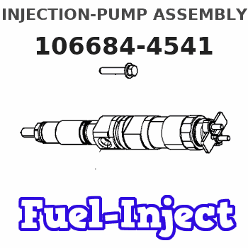
Information injection-pump assembly
BOSCH
F 019 Z20 203
f019z20203
ZEXEL
106684-4541
1066844541
MITSUBISHI-HEAV
3266500270
3266500270
Rating:
Service parts 106684-4541 INJECTION-PUMP ASSEMBLY:
1.
_
3.
GOVERNOR
5.
AUTOM. ADVANCE MECHANIS
8.
_
9.
_
11.
Nozzle and Holder
12.
Open Pre:MPa(Kqf/cm2)
29.4{300}
15.
NOZZLE SET
Include in #1:
106684-4541
as INJECTION-PUMP ASSEMBLY
Cross reference number
BOSCH
F 019 Z20 203
f019z20203
ZEXEL
106684-4541
1066844541
MITSUBISHI-HEAV
3266500270
3266500270
Zexel num
Bosch num
Firm num
Name
F 019 Z20 203
3266500270 MITSUBISHI-HEAV
INJECTION-PUMP ASSEMBLY
S12A2 * K 14CA INJECTION PUMP ASSY PE6P,6PD PE
S12A2 * K 14CA INJECTION PUMP ASSY PE6P,6PD PE
Calibration Data:
Adjustment conditions
Test oil
1404 Test oil ISO4113 or {SAEJ967d}
1404 Test oil ISO4113 or {SAEJ967d}
Test oil temperature
degC
40
40
45
Nozzle and nozzle holder
105780-8130
Bosch type code
EFEP215A
Nozzle
105780-0050
Bosch type code
DN6TD119NP1T
Nozzle holder
105780-2090
Bosch type code
EFEP215
Opening pressure
MPa
17.2
Opening pressure
kgf/cm2
175
Injection pipe
Outer diameter - inner diameter - length (mm) mm 8-4-1000
Outer diameter - inner diameter - length (mm) mm 8-4-1000
Overflow valve
131424-3420
Overflow valve opening pressure
kPa
255
221
289
Overflow valve opening pressure
kgf/cm2
2.6
2.25
2.95
Tester oil delivery pressure
kPa
255
255
255
Tester oil delivery pressure
kgf/cm2
2.6
2.6
2.6
Direction of rotation (viewed from drive side)
Left L
Left L
Injection timing adjustment
Direction of rotation (viewed from drive side)
Left L
Left L
Injection order
1-5-3-6-
2-4
Pre-stroke
mm
2.8
2.75
2.85
Beginning of injection position
Opposite to the driving side NO.1
Opposite to the driving side NO.1
Difference between angles 1
Cal 1-5 deg. 60 59.5 60.5
Cal 1-5 deg. 60 59.5 60.5
Difference between angles 2
Cal 1-3 deg. 120 119.5 120.5
Cal 1-3 deg. 120 119.5 120.5
Difference between angles 3
Cal 1-6 deg. 180 179.5 180.5
Cal 1-6 deg. 180 179.5 180.5
Difference between angles 4
Cyl.1-2 deg. 240 239.5 240.5
Cyl.1-2 deg. 240 239.5 240.5
Difference between angles 5
Cal 1-4 deg. 300 299.5 300.5
Cal 1-4 deg. 300 299.5 300.5
Injection quantity adjustment
Adjusting point
A
Rack position
14.8
Pump speed
r/min
750
750
750
Average injection quantity
mm3/st.
539
530
548
Max. variation between cylinders
%
0
-3
3
Basic
*
Fixing the rack
*
Rack limit
*
Injection quantity adjustment_02
Adjusting point
-
Rack position
6.9+-0.5
Pump speed
r/min
375
375
375
Average injection quantity
mm3/st.
28.5
25.5
31.5
Max. variation between cylinders
%
0
-7
7
Fixing the rack
*
Test data Ex:
0000001501 RACK SENSOR
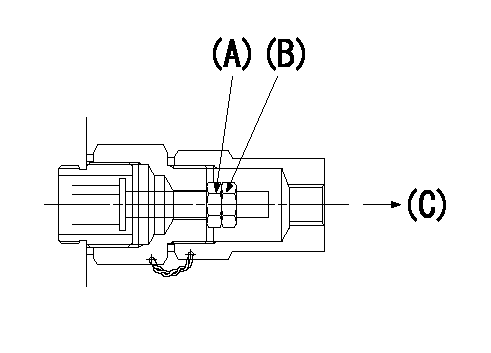
Nut A
(B) Nut
(C) Injection quantity decrease direction
1. Driven side rack limit mechanism adjustment procedure (for row R)
(1)Set the rack limit at adjusting point A using the two nuts (A) and (B) on the driven side end of the rack.
----------
----------
----------
----------
0000001601 RACK SENSOR
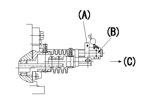
Plate A
(B) Nut
(C) Injection quantity increase direction
1. Drive side rack limit mechanism adjustment procedure (for row L)
(1)Set the rack limit at adjusting point A using the plate (A) above the drive side rack and the nut (B).
----------
----------
----------
----------
Timing setting

(1)Pump vertical direction
(2)Coupling's key groove position at No 1 cylinder's beginning of injection
(3)-
(4)-
----------
----------
a=(20deg)
----------
----------
a=(20deg)
Information:
Engine Mounts
Inspect
Inspect the engine mounts for deterioration and proper bolt torque. Engine vibration may be caused by improper engine mounting and/or engine mount deterioration. Any engine mount showing deterioration should be replaced. Refer to the Torque Specifications section of this publication for recommended bolt torque values. See the Marine Engine Application and Installation Guide for more information.Crankshaft Vibration Damper
Inspect
Damage to, or failure of, the crankshaft vibration damper will increase torsional vibrations and result in damage to the crankshaft and other engine components. A deteriorating damper will cause excessive gear train noise at variable points in the speed range.The damper is mounted to the crankshaft, located behind the belt guard on the front of the engine.Removal and Installation
Refer to the Service Manual for the damper removal procedure and for the damper installation procedure.Visconic Damper
The visconic damper has a weight, located inside a fluid filled case. The weight moves in the case to limit torsional vibration. Inspect the damper for evidence of dents, cracks or leaks of the fluid.Replace the damper if the damper is dented, cracked, or leaking. Refer to the Service Manual or contact your Caterpillar dealer for damper replacement.Valve Lash
Check/Adjust
Initial valve lash adjustment on new, rebuilt or remanufactured engines is recommended at the first scheduled oil change interval due to initial wear and seating of valve train components.Subsequent adjustments should be made at Every 3000 Hour interval.This maintenance is recommended by Caterpillar as part of a lubrication and preventive maintenance schedule to provide maximum engine life.
Only qualified service personnel should perform this maintenance. Refer to the Service Manual or your Caterpillar dealer for the complete valve lash adjustment procedure.
Be sure the engine cannot be started while this maintenance is being performed. To prevent possible injury, do not use the starting motor to turn the flywheel.Hot engine components can cause burns. Allow additional time for the engine to cool before measuring/adjusting valve lash clearance.
Operation of Caterpillar engines with improper valve adjustments will reduce engine efficiency. This reduced efficiency could result in excessive fuel usage and/or shortened engine component life.
Valve Rotators
When inspecting the valve rotators, protective glasses or face shield and protective clothing must be worn, to prevent being burned by hot oil or spray.
A valve rotator which does not operate properly will accelerate valve face wear and valve seat wear and shorten valve life. If a damaged rotator is not replaced, valve face guttering could result and cause pieces of the valve to fall into the cylinder. This can cause piston and cylinder head damage.
After setting the valve lash and before installing the valve covers:1. Start the engine. Follow the engine starting procedure in this manual. Operate the engine at low idle.2. Observe the top surface of each valve rotator. Each valve rotator should turn slightly each time the valve closes.If a valve fails to rotate, contact your Caterpillar dealer.Fuel Ratio Control, Set Point, and Low Idle
Check/Adjust
The fuel ratio control limits the amount of fuel to the cylinders during acceleration. This affects the amount of exhaust smoke. The
Inspect
Inspect the engine mounts for deterioration and proper bolt torque. Engine vibration may be caused by improper engine mounting and/or engine mount deterioration. Any engine mount showing deterioration should be replaced. Refer to the Torque Specifications section of this publication for recommended bolt torque values. See the Marine Engine Application and Installation Guide for more information.Crankshaft Vibration Damper
Inspect
Damage to, or failure of, the crankshaft vibration damper will increase torsional vibrations and result in damage to the crankshaft and other engine components. A deteriorating damper will cause excessive gear train noise at variable points in the speed range.The damper is mounted to the crankshaft, located behind the belt guard on the front of the engine.Removal and Installation
Refer to the Service Manual for the damper removal procedure and for the damper installation procedure.Visconic Damper
The visconic damper has a weight, located inside a fluid filled case. The weight moves in the case to limit torsional vibration. Inspect the damper for evidence of dents, cracks or leaks of the fluid.Replace the damper if the damper is dented, cracked, or leaking. Refer to the Service Manual or contact your Caterpillar dealer for damper replacement.Valve Lash
Check/Adjust
Initial valve lash adjustment on new, rebuilt or remanufactured engines is recommended at the first scheduled oil change interval due to initial wear and seating of valve train components.Subsequent adjustments should be made at Every 3000 Hour interval.This maintenance is recommended by Caterpillar as part of a lubrication and preventive maintenance schedule to provide maximum engine life.
Only qualified service personnel should perform this maintenance. Refer to the Service Manual or your Caterpillar dealer for the complete valve lash adjustment procedure.
Be sure the engine cannot be started while this maintenance is being performed. To prevent possible injury, do not use the starting motor to turn the flywheel.Hot engine components can cause burns. Allow additional time for the engine to cool before measuring/adjusting valve lash clearance.
Operation of Caterpillar engines with improper valve adjustments will reduce engine efficiency. This reduced efficiency could result in excessive fuel usage and/or shortened engine component life.
Valve Rotators
When inspecting the valve rotators, protective glasses or face shield and protective clothing must be worn, to prevent being burned by hot oil or spray.
A valve rotator which does not operate properly will accelerate valve face wear and valve seat wear and shorten valve life. If a damaged rotator is not replaced, valve face guttering could result and cause pieces of the valve to fall into the cylinder. This can cause piston and cylinder head damage.
After setting the valve lash and before installing the valve covers:1. Start the engine. Follow the engine starting procedure in this manual. Operate the engine at low idle.2. Observe the top surface of each valve rotator. Each valve rotator should turn slightly each time the valve closes.If a valve fails to rotate, contact your Caterpillar dealer.Fuel Ratio Control, Set Point, and Low Idle
Check/Adjust
The fuel ratio control limits the amount of fuel to the cylinders during acceleration. This affects the amount of exhaust smoke. The