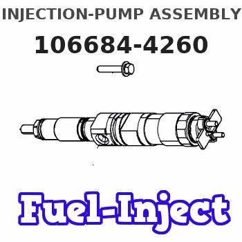
Information injection-pump assembly
BOSCH
9 400 610 989
9400610989
ZEXEL
106684-4260
1066844260
Rating:
Service parts 106684-4260 INJECTION-PUMP ASSEMBLY:
1.
_
3.
GOVERNOR
5.
AUTOM. ADVANCE MECHANIS
7.
COUPLING PLATE
8.
_
9.
_
11.
Nozzle and Holder
6212-11-3900
12.
Open Pre:MPa(Kqf/cm2)
24.5{250}
15.
NOZZLE SET
Include in #1:
106684-4260
as INJECTION-PUMP ASSEMBLY
Cross reference number
BOSCH
9 400 610 989
9400610989
ZEXEL
106684-4260
1066844260
Zexel num
Bosch num
Firm num
Name
Calibration Data:
Adjustment conditions
Test oil
1404 Test oil ISO4113 or {SAEJ967d}
1404 Test oil ISO4113 or {SAEJ967d}
Test oil temperature
degC
40
40
45
Nozzle and nozzle holder
105780-8130
Bosch type code
EFEP215A
Nozzle
105780-0050
Bosch type code
DN6TD119NP1T
Nozzle holder
105780-2090
Bosch type code
EFEP215
Opening pressure
MPa
17.2
Opening pressure
kgf/cm2
175
Injection pipe
Outer diameter - inner diameter - length (mm) mm 8-4-1000
Outer diameter - inner diameter - length (mm) mm 8-4-1000
Overflow valve
131425-1620
Overflow valve opening pressure
kPa
255
221
289
Overflow valve opening pressure
kgf/cm2
2.6
2.25
2.95
Tester oil delivery pressure
kPa
157
157
157
Tester oil delivery pressure
kgf/cm2
1.6
1.6
1.6
Direction of rotation (viewed from drive side)
Right R
Right R
Injection timing adjustment
Direction of rotation (viewed from drive side)
Right R
Right R
Injection order
1-5-3-6-
2-4
Pre-stroke
mm
3
2.95
3.05
Beginning of injection position
Drive side NO.1
Drive side NO.1
Difference between angles 1
Cal 1-5 deg. 60 59.5 60.5
Cal 1-5 deg. 60 59.5 60.5
Difference between angles 2
Cal 1-3 deg. 120 119.5 120.5
Cal 1-3 deg. 120 119.5 120.5
Difference between angles 3
Cal 1-6 deg. 180 179.5 180.5
Cal 1-6 deg. 180 179.5 180.5
Difference between angles 4
Cyl.1-2 deg. 240 239.5 240.5
Cyl.1-2 deg. 240 239.5 240.5
Difference between angles 5
Cal 1-4 deg. 300 299.5 300.5
Cal 1-4 deg. 300 299.5 300.5
Injection quantity adjustment
Adjusting point
A
Rack position
15.2
Pump speed
r/min
750
750
750
Average injection quantity
mm3/st.
495
490
500
Max. variation between cylinders
%
0
-3
3
Basic
*
Fixing the rack
*
Remarks
Standard point A's rack position same as 106682-9680 in row L.
Standard point A's rack position same as 106682-9680 in row L.
Injection quantity adjustment_02
Adjusting point
-
Rack position
7.5+-0.5
Pump speed
r/min
400
400
400
Average injection quantity
mm3/st.
18.5
17
20
Max. variation between cylinders
%
0
-15
15
Fixing the rack
*
Injection quantity adjustment_03
Adjusting point
-
Rack position
16.3+0.2
Pump speed
r/min
100
100
100
Average injection quantity
mm3/st.
445
445
485
Fixing the rack
*
Rack limit
*
Test data Ex:
Timing setting

(1)Pump vertical direction
(2)Coupling's key groove position at No 1 cylinder's beginning of injection
(3)-
(4)-
----------
----------
a=(150deg)
----------
----------
a=(150deg)
Information:
Under the Hood Inspection
For maximum service life of your truck engine, make a thorough under the hood inspection before starting the engine. Look for such items as oil or coolant leaks, loose bolts, worn belts and trash build-up. Remove trash build-up and have repairs made as needed.Perform required Daily maintenance before starting the engine.
Each time any significant quantity of oil (or other fluid) is spilled on or near the engine it should be cleaned up. Accumulated grease and oil on an engine is a fire hazard. Remove this debris with steam cleaning or high pressure water at PM Level 2 or every 6000 hours.Wipe clean all fittings, caps and plugs before servicing.
Starting the Engine
Do not store starting fluid containers in the cab. Failure to do so, could result in an explosion and/or fire and possible personal injury.If equipped with an electrically or fuel ignited manifold heater, DO NOT use ether.If equipped with Flammstart, DO NOT use ether.
Startability will be improved at temperatures below +32°F (0°C) by the use of a starting aid (ether) or use of a cylinder block coolant heater or other means to heat the crankcase oil. This will help alleviate white smoke and misfire during cold weather start-up.Use ether when temperatures are below 32°F (0°C) for cold weather starting purposes only.
When using starting fluid, follow the manufacturer's instructions carefully, use it sparingly and spray it ONLY WHILE CRANKING THE ENGINE. Excessive ether can cause piston and ring damage.Use ether for cold starting purposes only.
If the engine fails to start within 30 seconds, release the starter switch and wait two minutes to allow the starter motor to cool before using it again.Start the engine using the following procedure:1. Place the transmission in NEUTRAL and disengage the flywheel clutch (if equipped) to remove the transmission drag and prevent movement of the truck.Depressing the clutch in cold weather can mean the difference between starting and not starting. Depressing the clutch in warm weather produces faster starts and reduces battery drain.2. Turn the ignition switch to the ON position and push the crank button or turn the ignition switch to the START position.It may be necessary to push down on the throttle to get the fuel rack to move to the "fuel on" position for mechanical fuel system engines.
DO NOT PUSH DOWN OR HOLD THE THROTTLE DOWN while cranking the Electronic engine. The system will automatically provide the correct amount of fuel to start the engine.
3. Crank the engine. If the engine fails to start in 30 seconds, release the starting (ignition) switch and wait two minutes to allow the starter motor to cool before using it again. The Electronic engine may need to crank slightly longer than a mechanically governed engine, because some oil pressure is required for the electronic actuator to move the rack. The CHECK ENGINE/DIAGNOSTIC lamp should be ON while the engine is cranking, but should go OFF after engine oil pressure is achieved.
Do not increase engine speed until the oil pressure gauge indicates normal.