Information injection-pump assembly
BOSCH
9 400 617 651
9400617651
ZEXEL
106682-9960
1066829960
KOMATSU
6162752180
6162752180

Rating:
Service parts 106682-9960 INJECTION-PUMP ASSEMBLY:
1.
_
5.
AUTOM. ADVANCE MECHANIS
7.
COUPLING PLATE
8.
_
9.
_
11.
Nozzle and Holder
12.
Open Pre:MPa(Kqf/cm2)
26.0{265}
15.
NOZZLE SET
Include in #1:
106682-9960
as INJECTION-PUMP ASSEMBLY
Cross reference number
BOSCH
9 400 617 651
9400617651
ZEXEL
106682-9960
1066829960
KOMATSU
6162752180
6162752180
Zexel num
Bosch num
Firm num
Name
106682-9960
9 400 617 651
6162752180 KOMATSU
INJECTION-PUMP ASSEMBLY
SA6D170 K
SA6D170 K
Calibration Data:
Adjustment conditions
Test oil
1404 Test oil ISO4113 or {SAEJ967d}
1404 Test oil ISO4113 or {SAEJ967d}
Test oil temperature
degC
40
40
45
Nozzle and nozzle holder
105780-8130
Bosch type code
EFEP215A
Nozzle
105780-0050
Bosch type code
DN6TD119NP1T
Nozzle holder
105780-2090
Bosch type code
EFEP215
Opening pressure
MPa
17.2
Opening pressure
kgf/cm2
175
Injection pipe
Outer diameter - inner diameter - length (mm) mm 8-4-1000
Outer diameter - inner diameter - length (mm) mm 8-4-1000
Overflow valve
131425-1620
Overflow valve opening pressure
kPa
255
221
289
Overflow valve opening pressure
kgf/cm2
2.6
2.25
2.95
Tester oil delivery pressure
kPa
157
157
157
Tester oil delivery pressure
kgf/cm2
1.6
1.6
1.6
Direction of rotation (viewed from drive side)
Left L
Left L
Injection timing adjustment
Direction of rotation (viewed from drive side)
Left L
Left L
Injection order
1-5-3-6-
2-4
Pre-stroke
mm
2.8
2.75
2.85
Beginning of injection position
Drive side NO.1
Drive side NO.1
Difference between angles 1
Cal 1-5 deg. 60 59.5 60.5
Cal 1-5 deg. 60 59.5 60.5
Difference between angles 2
Cal 1-3 deg. 120 119.5 120.5
Cal 1-3 deg. 120 119.5 120.5
Difference between angles 3
Cal 1-6 deg. 180 179.5 180.5
Cal 1-6 deg. 180 179.5 180.5
Difference between angles 4
Cyl.1-2 deg. 240 239.5 240.5
Cyl.1-2 deg. 240 239.5 240.5
Difference between angles 5
Cal 1-4 deg. 300 299.5 300.5
Cal 1-4 deg. 300 299.5 300.5
Injection quantity adjustment
Adjusting point
A
Rack position
13.8
Pump speed
r/min
900
900
900
Average injection quantity
mm3/st.
429
425
433
Max. variation between cylinders
%
0
-3
3
Basic
*
Fixing the lever
*
Boost pressure
kPa
74.6
74.6
Boost pressure
mmHg
560
560
Injection quantity adjustment_02
Adjusting point
C
Rack position
7.5+-0.5
Pump speed
r/min
375
375
375
Average injection quantity
mm3/st.
24
19
29
Max. variation between cylinders
%
0
-15
15
Fixing the rack
*
Boost pressure
kPa
0
0
0
Boost pressure
mmHg
0
0
0
Boost compensator adjustment
Pump speed
r/min
600
600
600
Rack position
R1-2.8
Boost pressure
kPa
25.3
22.6
28
Boost pressure
mmHg
190
170
210
Boost compensator adjustment_02
Pump speed
r/min
600
600
600
Rack position
R1(14.65
)
Boost pressure
kPa
61.3
54.6
68
Boost pressure
mmHg
460
410
510
Test data Ex:
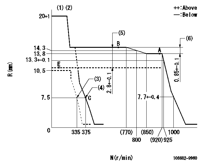
Governor adjustment

N:Pump speed
R:Rack position (mm)
(1)Target notch: K
(2)Tolerance for racks not indicated: +-0.05mm.
(3)Set idle sub-spring
(4)Main spring setting
(5)Boost compensator stroke
(6)Rack difference between N = N1 and N = N2
----------
K=11 N1=900r/min N2=650r/min
----------
----------
K=11 N1=900r/min N2=650r/min
----------
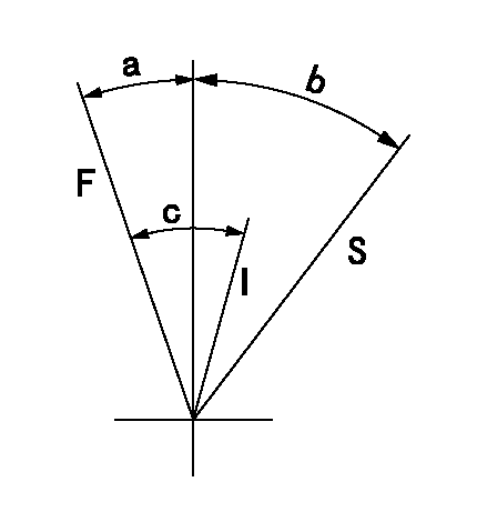
Speed control lever angle

F:Full speed
I:Idle
S:Stop
----------
----------
a=12deg+-5deg b=27deg+-3deg c=26deg+-5deg
----------
----------
a=12deg+-5deg b=27deg+-3deg c=26deg+-5deg
0000001501 LEVER

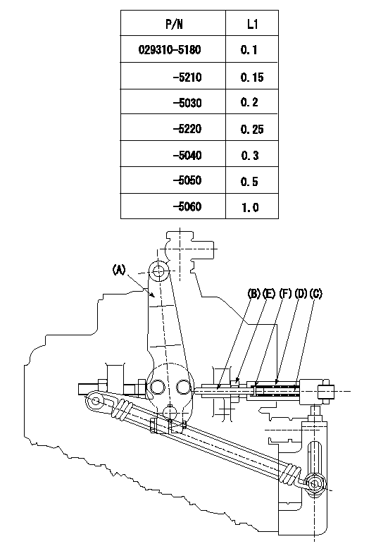
Speed lever adjustment
1. (1) For idling hold the speed lever (a) against the push rod (B).
(2)At this time, confirm that the spring (C) is not bent by the operating torque of the speed lever.
2. (1) To stop, bend the spring (C) using the speed lever.
(2)Position the rack at L2. (Adjustment is performed using the shim (F).)
(3)Set and fix using lock nut (E) so that it contacts the guide screw (D).
3. Confirm that the speed lever returns to the idling position when pulled in the stop direction and then released.
----------
L2=0.2~2mm
----------
----------
L2=0.2~2mm
----------
Timing setting

(1)Pump vertical direction
(2)Coupling's key groove position at No 1 cylinder's beginning of injection
(3)-
(4)-
----------
----------
a=(40deg)
----------
----------
a=(40deg)
Information:
Cooling System
Clean/Flush Coolant
Do not perform this maintenance until you read and understand the material in the Safety and Cooling System Specifications sections of this publication. This procedure is to be used for normal maintenance of cooling system surfaces to return to "like new" condition. For heavy build-up of scale and deposits, a severe acid-type, commercial cleaner or mechanical cleaning will be required.
1. Stop the engine and allow to cool. Loosen the radiator filler cap slowly and remove the cap to relieve pressure. 2. Remove the cooling system drain plug(s). Remove the drain plug (1) on bottom of water pump housing and/or radiator.Check water pump breather filter 4N1400 (2) for blockage or debris and replace if necessary.
Right Side View3. Open the cab heater valve to flush coolant from the cab heater. Remove the two block drain plugs from both sides of the engine. Allow coolant to drain.With the recent shortage and higher cost of new antifreeze and the disposal problems of used engine coolant, the interest in recycling the used engine coolant has sharply increased. Various methods have been proposed to reclaim used coolant for reuse in engine cooling systems.Filtering methods for reclaiming the used engine cooland do not reduce the level of chemicals in the water. The full distillation procedure is the only method acceptable by Caterpillar to reclaim the used coolant. The ethylene glycol and water obtained from this process can be treated with new chemical corrosion inhibitors to provide a like-new coolant.Commercial units are available to do this distillation process. Contact Caterpillar Service Technology Group: Outside Illinois: 1-800-542-TOOL Inside Illinois: 1-800-541-TOOL Canada: 1-800-523-TOOLRefer to Service Magazine article dated November 13, 1989 and/or Engine News article dated November 1989 for information regarding disposal and recycling of used coolant.4. Clean and install all drain plugs or close the drain valve. Refill the cooling system with clean water mixed with a 6 to 10 percent concentration of Caterpillar Cooling System Cleaner. Install radiator filler cap.Caterpillar Cooling System Cleaner is available through your Caterpillar dealer. A 9-12 gallon (33-47 L) cooling system capacity requires one gallon (3.8 L) of Caterpillar Cooling System Cleaner to accommodate the 6-10 percent concentration.5. Start and run the engine to circulate fluid in the cooling system for 1 1/2 hours.6. Stop the engine, remove radiator filler cap and cooling system drain plugs.7. Drain the cleaning solution. Flush the cooling system with clean water until draining water is clear. Clean and install all drain plugs and/or close the drain valve.8. Mix a solution of acceptable water and Caterpillar Antifreeze (which contains supplemental coolant additive). If NOT using Caterpillar Antifreeze, add 1 U.S. quart (1 L) of Caterpillar Supplemental Coolant Additive for every 8 U.S. gal (30 L) of cooling system capacity OR replace maintenance element with a precharge element only. Supplemental Coolant Additive or a coolant additive element (if equipped) should only be used when NOT refilling cooling system with Caterpillar Antifreeze. Refer to the topic Cooling System Specifications in this publication for all information regarding
Have questions with 106682-9960?
Group cross 106682-9960 ZEXEL
Mitsubishi-Heav
Komatsu
Komatsu
Komatsu
106682-9960
9 400 617 651
6162752180
INJECTION-PUMP ASSEMBLY
SA6D170
SA6D170