Information injection-pump assembly
BOSCH
9 400 619 779
9400619779
ZEXEL
106682-9781
1066829781

Rating:
Service parts 106682-9781 INJECTION-PUMP ASSEMBLY:
1.
_
5.
AUTOM. ADVANCE MECHANIS
7.
COUPLING PLATE
8.
_
9.
_
11.
Nozzle and Holder
12.
Open Pre:MPa(Kqf/cm2)
24.5{250}
15.
NOZZLE SET
Include in #1:
106682-9781
as INJECTION-PUMP ASSEMBLY
Cross reference number
BOSCH
9 400 619 779
9400619779
ZEXEL
106682-9781
1066829781
Zexel num
Bosch num
Firm num
Name
Calibration Data:
Adjustment conditions
Test oil
1404 Test oil ISO4113 or {SAEJ967d}
1404 Test oil ISO4113 or {SAEJ967d}
Test oil temperature
degC
40
40
45
Nozzle and nozzle holder
105780-8130
Bosch type code
EFEP215A
Nozzle
105780-0050
Bosch type code
DN6TD119NP1T
Nozzle holder
105780-2090
Bosch type code
EFEP215
Opening pressure
MPa
17.2
Opening pressure
kgf/cm2
175
Injection pipe
Outer diameter - inner diameter - length (mm) mm 8-4-1000
Outer diameter - inner diameter - length (mm) mm 8-4-1000
Overflow valve
131425-1620
Overflow valve opening pressure
kPa
255
221
289
Overflow valve opening pressure
kgf/cm2
2.6
2.25
2.95
Tester oil delivery pressure
kPa
157
157
157
Tester oil delivery pressure
kgf/cm2
1.6
1.6
1.6
Direction of rotation (viewed from drive side)
Right R
Right R
Injection timing adjustment
Direction of rotation (viewed from drive side)
Right R
Right R
Injection order
1-5-3-6-
2-4
Pre-stroke
mm
3.5
3.45
3.55
Beginning of injection position
Drive side NO.1
Drive side NO.1
Difference between angles 1
Cal 1-5 deg. 60 59.5 60.5
Cal 1-5 deg. 60 59.5 60.5
Difference between angles 2
Cal 1-3 deg. 120 119.5 120.5
Cal 1-3 deg. 120 119.5 120.5
Difference between angles 3
Cal 1-6 deg. 180 179.5 180.5
Cal 1-6 deg. 180 179.5 180.5
Difference between angles 4
Cyl.1-2 deg. 240 239.5 240.5
Cyl.1-2 deg. 240 239.5 240.5
Difference between angles 5
Cal 1-4 deg. 300 299.5 300.5
Cal 1-4 deg. 300 299.5 300.5
Injection quantity adjustment
Adjusting point
A
Rack position
13.5
Pump speed
r/min
1000
1000
1000
Average injection quantity
mm3/st.
326
323
329
Max. variation between cylinders
%
0
-3
3
Basic
*
Fixing the lever
*
Boost pressure
kPa
70.6
70.6
Boost pressure
mmHg
530
530
Remarks
Standard point A's rack position same as row R
Standard point A's rack position same as row R
Injection quantity adjustment_02
Adjusting point
C
Rack position
7.6+-0.5
Pump speed
r/min
350
350
350
Average injection quantity
mm3/st.
13
11.5
14.5
Max. variation between cylinders
%
0
-15
15
Fixing the rack
*
Boost pressure
kPa
0
0
0
Boost pressure
mmHg
0
0
0
Boost compensator adjustment
Pump speed
r/min
650
650
650
Rack position
R1-2.6
Boost pressure
kPa
8
5.3
10.7
Boost pressure
mmHg
60
40
80
Boost compensator adjustment_02
Pump speed
r/min
650
650
650
Rack position
R1(14.9)
Boost pressure
kPa
57.3
50.6
64
Boost pressure
mmHg
430
380
480
Test data Ex:
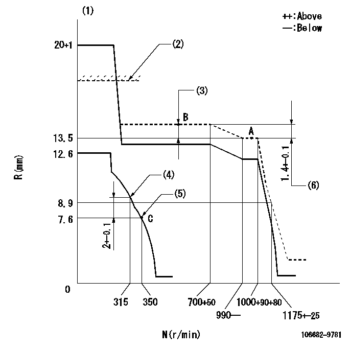
Governor adjustment

N:Pump speed
R:Rack position (mm)
(1)Target notch: K
(2)RACK LIMIT for 106684-4311
(3)Boost compensator stroke: BCL
(4)Set the No 1 idle sub spring.
(5)Set the 2nd idle sub spring.
(6)Rack difference between N = N1 and N = N2
----------
K=22 BCL=2.6+-0.1mm N1=1000r/min N2=650r/min
----------
----------
K=22 BCL=2.6+-0.1mm N1=1000r/min N2=650r/min
----------
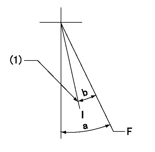
Speed control lever angle

F:Full speed
I:Idle
(1)Stopper bolt setting
----------
----------
a=35deg+-5deg b=27deg+-5deg
----------
----------
a=35deg+-5deg b=27deg+-5deg
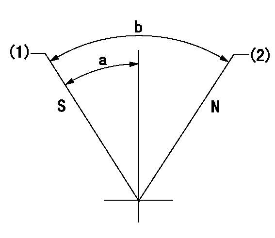
Stop lever angle

N:Pump normal
S:Stop the pump.
(1)Pump speed aa and rack position bb (to be sealed at delivery)
(2)-
----------
aa=0r/min bb=1-0.5mm
----------
a=29deg+-5deg b=(73deg)
----------
aa=0r/min bb=1-0.5mm
----------
a=29deg+-5deg b=(73deg)
Timing setting

(1)Pump vertical direction
(2)Coupling's key groove position at No 1 cylinder's beginning of injection
(3)-
(4)-
----------
----------
a=(30deg)
----------
----------
a=(30deg)
Information:
Diagnostic Lamp
A DIAGNOSTIC lamp may be included with your engine package. The DIAGNOSTIC lamp indicates an engine diagnostic condition or an electronic governing/control system fault. In most cases a diagnostic code will be stored in permanent memory within the ECM. The diagnostic code can be retrieved by either of two methods; 1) electronic service tool or 2) use the DIAGNOSTIC lamp.The engine may be equipped with a DIAGNOSTIC lamp that automatically flashes an active fault code when there is power to the ECM. ACTIVE Codes - represent problem(s) that currently exist and should be investigated first. If a code is active, the Diagnostic lamp will illuminate and blink every five seconds. LOGGED Codes - represent intermittent problem(s) which may have been temporary or repaired since the time code was logged. These codes do not indicate a repair is needed, but instead are guides or signals when an intermittent situation exists, which could be used to troubleshoot and analyze potential problems. In addition, some LOGGED Codes record events and performance history, rather than problems and/or failures.Diagnostic Flash Code Retrieval
If the DIAGNOSTIC lamp is ON during engine operation, the system has detected a system fault. Use the DIAGNOSTIC lamp or electronic service tool to identify the diagnostic code.The DIAGNOSTIC lamp will illuminate (ON) and blink every five seconds whenever a diagnostic fault is detected by the ECM. The lamp should also illuminate (ON) whenever the START switch is turned ON, but the engine is not running. This condition will test whether the lamp is operating correctly. The DIAGNOSTIC lamp will illuminate for five seconds and turn OFF for an intermittent fault (stays ON ONLY if there is an Active Diagnostic Code).If the DIAGNOSTIC lamp comes ON and stays ON after initial start-up, the ECM has detected a system fault. Use the lamp or the ECAP service tool to determine the diagnostic code.The DIAGNOSTIC lamp can be used to communicate the specific diagnostic fault. With the switch depressed, the DIAGNOSTIC lamp will begin to flash. The sequence of flashes represents the system diagnostic message. Count the first sequence of flashes to determine the first digit of the diagnostic code. After a two second pause, the second sequence of flashes will identify the second digit of the diagnostic code. Any additional diagnostic codes will follow (after a pause) and will be displayed in the same manner.Refer to the Electronic Troubleshooting Manual for troubleshooting ELECTRONIC SYSTEM problems, or for further information or assistance, contact your Caterpillar dealer. Permanent Fault Logging
The system provides Permanent Fault Logging. When the ECM generates a diagnostic code, it will log the code in permanent memory. The logged codes can then be retrieved using an electronic service tool.Intermittent Fault
If the diagnostic lamp comes ON during engine operation, and then goes out, an intermittent fault may be occurring. The electronic control engine system is equipped with permanent fault logging. It will automatically log (or remember) most intermittent faults to help a service technician diagnose an engine problem.If there are no