Information injection-pump assembly
BOSCH
F 019 Z10 542
f019z10542
ZEXEL
106682-9770
1066829770

Rating:
Service parts 106682-9770 INJECTION-PUMP ASSEMBLY:
1.
_
5.
AUTOM. ADVANCE MECHANIS
7.
COUPLING PLATE
8.
_
9.
_
11.
Nozzle and Holder
12.
Open Pre:MPa(Kqf/cm2)
24.5(250)
15.
NOZZLE SET
Include in #1:
106682-9770
as INJECTION-PUMP ASSEMBLY
Cross reference number
BOSCH
F 019 Z10 542
f019z10542
ZEXEL
106682-9770
1066829770
Zexel num
Bosch num
Firm num
Name
Calibration Data:
Adjustment conditions
Test oil
1404 Test oil ISO4113 or {SAEJ967d}
1404 Test oil ISO4113 or {SAEJ967d}
Test oil temperature
degC
40
40
45
Nozzle and nozzle holder
105780-8130
Bosch type code
EFEP215A
Nozzle
105780-0050
Bosch type code
DN6TD119NP1T
Nozzle holder
105780-2090
Bosch type code
EFEP215
Opening pressure
MPa
17.2
Opening pressure
kgf/cm2
175
Injection pipe
Outer diameter - inner diameter - length (mm) mm 8-4-1000
Outer diameter - inner diameter - length (mm) mm 8-4-1000
Overflow valve
131424-7120
Overflow valve opening pressure
kPa
255
221
289
Overflow valve opening pressure
kgf/cm2
2.6
2.25
2.95
Tester oil delivery pressure
kPa
157
157
157
Tester oil delivery pressure
kgf/cm2
1.6
1.6
1.6
Direction of rotation (viewed from drive side)
Right R
Right R
Injection timing adjustment
Direction of rotation (viewed from drive side)
Right R
Right R
Injection order
1-5-3-6-
2-4
Pre-stroke
mm
3.5
3.45
3.55
Beginning of injection position
Drive side NO.1
Drive side NO.1
Difference between angles 1
Cal 1-5 deg. 60 59.5 60.5
Cal 1-5 deg. 60 59.5 60.5
Difference between angles 2
Cal 1-3 deg. 120 119.5 120.5
Cal 1-3 deg. 120 119.5 120.5
Difference between angles 3
Cal 1-6 deg. 180 179.5 180.5
Cal 1-6 deg. 180 179.5 180.5
Difference between angles 4
Cyl.1-2 deg. 240 239.5 240.5
Cyl.1-2 deg. 240 239.5 240.5
Difference between angles 5
Cal 1-4 deg. 300 299.5 300.5
Cal 1-4 deg. 300 299.5 300.5
Injection quantity adjustment
Adjusting point
A
Rack position
13.7
Pump speed
r/min
1000
1000
1000
Average injection quantity
mm3/st.
324
321
327
Max. variation between cylinders
%
0
-3
3
Basic
*
Fixing the lever
*
Boost pressure
kPa
61.3
61.3
Boost pressure
mmHg
460
460
Remarks
Standard point A's rack position same as row R
Standard point A's rack position same as row R
Injection quantity adjustment_02
Adjusting point
-
Rack position
8.4+-0.5
Pump speed
r/min
325
325
325
Average injection quantity
mm3/st.
20
18.5
21.5
Max. variation between cylinders
%
0
-15
15
Fixing the rack
*
Boost pressure
kPa
0
0
0
Boost pressure
mmHg
0
0
0
Remarks
Adjust only variation between cylinders; adjust governor according to governor specifications.
Adjust only variation between cylinders; adjust governor according to governor specifications.
Boost compensator adjustment
Pump speed
r/min
600
600
600
Rack position
R1-2.3
Boost pressure
kPa
6.7
4
9.4
Boost pressure
mmHg
50
30
70
Boost compensator adjustment_02
Pump speed
r/min
600
600
600
Rack position
R1(15.3)
Boost pressure
kPa
48
41.3
54.7
Boost pressure
mmHg
360
310
410
Test data Ex:
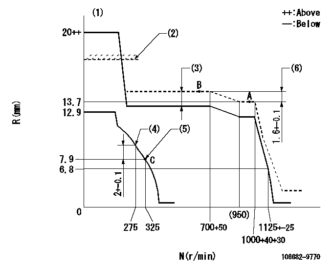
Governor adjustment

N:Pump speed
R:Rack position (mm)
(1)Target notch: K
(2)Rack limit for 106684-4300
(3)Boost compensator stroke: BCL
(4)Set the No 1 idle sub spring.
(5)Set the 2nd idle sub spring.
(6)Rack difference between N = N1 and N = N2
----------
K=23 BCL=2.3+-0.1mm N1=1000r/min N2=700r/min
----------
----------
K=23 BCL=2.3+-0.1mm N1=1000r/min N2=700r/min
----------
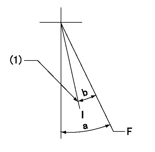
Speed control lever angle

F:Full speed
I:Idle
(1)Stopper bolt setting
----------
----------
a=32deg+-5deg b=25deg+-5deg
----------
----------
a=32deg+-5deg b=25deg+-5deg
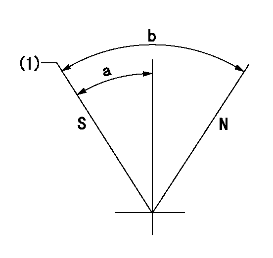
Stop lever angle

N:Pump normal
S:Stop the pump.
(1)Pump speed aa and rack position bb (to be sealed at delivery)
----------
aa=0r/min bb=1-0.5mm
----------
a=29deg+-5deg b=(73deg)
----------
aa=0r/min bb=1-0.5mm
----------
a=29deg+-5deg b=(73deg)
Timing setting

(1)Pump vertical direction
(2)Coupling's key groove position at No 1 cylinder's beginning of injection
(3)-
(4)-
----------
----------
a=(30deg)
----------
----------
a=(30deg)
Information:
Fuel System Information
Check the fuel level in the tank daily by observing the sight gauge, if equipped.
Fill the fuel tank at the end of each day of operation to drive out moist air and to prevent condensation. Maintain a fairly constant level in the tank (near the top) to avoid drawing moisture into the tank as the level decreases. Do not fill the tank to the top. Fuel expands as it gets warm and may overflow.Drain water and sediment from tank at the interval specified in the Maintenance Schedule.Do not fill fuel filters with fuel before installing them. Contaminated fuel will cause accelerated wear to fuel system parts.
Fuel Recommendations
Use only fuel as recommended in this section. The fuels recommended for use in Caterpillar engines are No.2-D diesel fuel and No.2 diesel fuel oil, although No. 1 diesel fuel grades are acceptable. The following fuel specifications are some of the worldwide fuels which may meet the requirements. Caterpillar Diesel Engines are capable of burning a wide range of distillate fuels. The use of clean, stable blends of distillate fuel which meet the following requirements will provide quality engine service life. The maximum allowable temperature for fuel to the engine is 65.6°C (150°F). The fuel cools the ECM and this allows for maximum electronic component life.Sulfur
The percentage of sulfur in the fuel will affect the engine oil recommendations. Fuel sulfur is chemically changed during combustion to form both sulfurous and sulfuric acid. These acids chemically attack metal surfaces and cause corrosive wear.Certain additives used in lubricating oils contain alkaline compounds that are formulated to neutralize these acids. The measure of this reserve alkalinity in a lubricating oil is known as its Total Base Number (TBN). TBN values are essential to neutralize the acids from combustion gases and to minimize corrosive wear.Fuels containing 0.5 percent or less sulfur may be used with recommended crankcase oil drain intervals using API CF-4 performance oils. With sulfur above the 0.5 percent level, use API CF-4 performance oils with an ASTM D-2896 Total Base Number (TBN) of 10 times the fuel sulfur for normal oil drain intervals.Caterpillar recommends infrared analysis (in conjunction with wear metal analysis) of used oil in determining the effectiveness of oil TBN and acid neutralization. The Caterpillar dealer S O S program provides this information. Regular oil analysis (S O S) will provide information to monitor oil properties and engine wear metals to maintain successful engine protection and establish oil drain intervals.Periodically request fuel sulfur content information from your fuel supplier. Fuel sulfur content can change with each bulk delivery. ASTM D-2896 can normally be found at your local technological society, library or college.Any American Petroleum Institute (API) classification performance oil should have sufficient TBN for fuels with less than 0.5 percent sulfur. Fuels containing 0.5 percent or less sulfur may be used with recommended crankcase oil drain intervals using API CF-4 performance oils.Additives
Fuel additives are generally not recommended nor needed for the specified fuels listed. Cetane improvers can be used