Information injection-pump assembly
ZEXEL
106682-9590
1066829590
Rating:
Service parts 106682-9590 INJECTION-PUMP ASSEMBLY:
1.
_
5.
AUTOM. ADVANCE MECHANIS
7.
COUPLING PLATE
8.
_
9.
_
11.
Nozzle and Holder
6212-12-3300
12.
Open Pre:MPa(Kqf/cm2)
24.5{250}
15.
NOZZLE SET
Include in #1:
106682-9590
as INJECTION-PUMP ASSEMBLY
Cross reference number
ZEXEL
106682-9590
1066829590
Zexel num
Bosch num
Firm num
Name
106682-9590
INJECTION-PUMP ASSEMBLY
Calibration Data:
Adjustment conditions
Test oil
1404 Test oil ISO4113 or {SAEJ967d}
1404 Test oil ISO4113 or {SAEJ967d}
Test oil temperature
degC
40
40
45
Nozzle and nozzle holder
105780-8130
Bosch type code
EFEP215A
Nozzle
105780-0050
Bosch type code
DN6TD119NP1T
Nozzle holder
105780-2090
Bosch type code
EFEP215
Opening pressure
MPa
17.2
Opening pressure
kgf/cm2
175
Injection pipe
Outer diameter - inner diameter - length (mm) mm 8-4-1000
Outer diameter - inner diameter - length (mm) mm 8-4-1000
Overflow valve
131425-1620
Overflow valve opening pressure
kPa
255
221
289
Overflow valve opening pressure
kgf/cm2
2.6
2.25
2.95
Tester oil delivery pressure
kPa
157
157
157
Tester oil delivery pressure
kgf/cm2
1.6
1.6
1.6
Direction of rotation (viewed from drive side)
Right R
Right R
Injection timing adjustment
Direction of rotation (viewed from drive side)
Right R
Right R
Injection order
1-5-3-6-
2-4
Pre-stroke
mm
3.3
3.25
3.35
Beginning of injection position
Drive side NO.1
Drive side NO.1
Difference between angles 1
Cal 1-5 deg. 60 59.5 60.5
Cal 1-5 deg. 60 59.5 60.5
Difference between angles 2
Cal 1-3 deg. 120 119.5 120.5
Cal 1-3 deg. 120 119.5 120.5
Difference between angles 3
Cal 1-6 deg. 180 179.5 180.5
Cal 1-6 deg. 180 179.5 180.5
Difference between angles 4
Cyl.1-2 deg. 240 239.5 240.5
Cyl.1-2 deg. 240 239.5 240.5
Difference between angles 5
Cal 1-4 deg. 300 299.5 300.5
Cal 1-4 deg. 300 299.5 300.5
Injection quantity adjustment
Adjusting point
A
Rack position
12.7
Pump speed
r/min
900
900
900
Average injection quantity
mm3/st.
348
343
353
Max. variation between cylinders
%
0
-3
3
Basic
*
Fixing the rack
*
Injection quantity adjustment_02
Adjusting point
B
Rack position
12.2
Pump speed
r/min
750
750
750
Average injection quantity
mm3/st.
304
298
310
Fixing the rack
*
Injection quantity adjustment_03
Adjusting point
C
Rack position
6.8+-0.5
Pump speed
r/min
405
405
405
Average injection quantity
mm3/st.
8.5
7
10
Max. variation between cylinders
%
0
-15
15
Fixing the rack
*
Injection quantity adjustment_04
Adjusting point
E
Rack position
-
Pump speed
r/min
100
100
100
Average injection quantity
mm3/st.
405
395
415
Fixing the lever
*
Rack limit
*
Test data Ex:
Governor adjustment
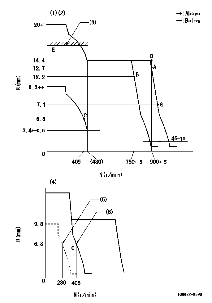
N:Pump speed
R:Rack position (mm)
(1)Minimum - maximum speed specification
(2)Target notch: K
(3)RACK LIMIT
(4)Variable speed specification: idling adjustment
(5)Set idle sub-spring
(6)Main spring setting
----------
K=18
----------
----------
K=18
----------
Speed control lever angle
F:Full speed
I:Idle
(1)Set the pump speed at aa
(2)Set the pump speed at bb.
(3)Stopper bolt setting
----------
aa=750r/min bb=900r/min
----------
a=10deg+-5deg b=14deg+-5deg c=28deg+-5deg
----------
aa=750r/min bb=900r/min
----------
a=10deg+-5deg b=14deg+-5deg c=28deg+-5deg
0000000901
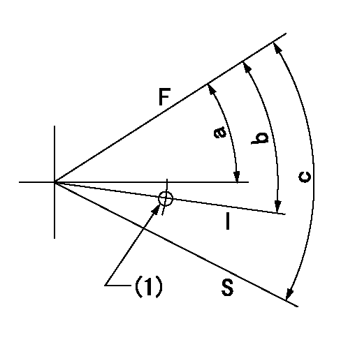
F:Full load
I:Idle
S:Stop
(1)Use the hole at R = aa
----------
aa=27mm
----------
a=26.5deg+-5deg b=29deg+-5deg c=53deg+-5deg
----------
aa=27mm
----------
a=26.5deg+-5deg b=29deg+-5deg c=53deg+-5deg
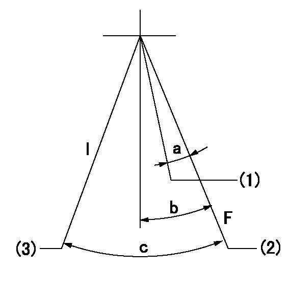
Timing setting

(1)Pump vertical direction
(2)Coupling's key groove position at No 1 cylinder's beginning of injection
(3)-
(4)-
----------
----------
a=(10deg)
----------
----------
a=(10deg)
Information:
Alarm Contactors
The engine is equipped with standard electrical overspeed switch which uses a flywheel housing mounted magnetic pickup. The magnetic pickup will close the circuit and the alarm will be activated when the engine exceeds the setpoint rpm. This engine may be equipped with a Coolant Level Alarm contactor. An Oil Pressure and Coolant Temperature Alarm contactors are optional.Alarm switches are electrically connected to an indicator light, bell or horn. When an alarm is activated, it is an indication of a potential problem and corrective measures must be taken before the situation becomes an emergency. While these alarm switches do not stop the engine, the problem should be investigated and corrective action taken to prevent engine damage.The alarm will continue until the condition is corrected. Then the light will turn off and the bell or horn will be silenced.To silence the bell or horn while repairs are being made, a two-way switch and a red indicator light may be installed. The red indicator light will come on when the alarm is turned off. The red light will stay on, to indicate that the engine is NOT protected, if the switch is left in the OFF position after the repairs have been made.Low Oil Pressure Switch (Early Engines)
The switch will not protect the system from rapid oil loss, caused by failures such as line breakage.
Low oil pressure switchThis device is usually mounted on the side of the engine. The oil lines are connected to the switch. Low oil pressure closes the switch. To reset the switch, push the RESET button in the junction box until it latches. After the engine starts and develops oil pressure, the button will move to the extended (running) position.
The button must be in the RUN position to protect the engine. If the button remains in the OFF position, the engine oil pump may not be developing normal oil pressure and proper checks should be made.
Manually operated systems require resetting of this switch before starting. Automatic start-stop systems use a pressure switch which resets itself.Low Oil Pressure Switch (Later Engines)
This switch does NOT require resetting. This switch is mounted in the oil manifold on the side of the block with the oil lines connected to it. Low oil pressure opens this switch to disconnect the electrical circuit to the shutoff solenoid. This prevents the battery from continuously energizing the solenoid while the engine is stopped.This switch is also used with the electric governor. On start-up, oil pressure will close the switch to allow the electric governor to increase engine speed.Marine Transmission Oil Temperature Switch
The switch is typically located in the oil line between the oil pump and the oil strainer or the oil filter of the marine transmission.High Coolant Water Temperature Switch
Coolant level must be maintained in order for the alarm to function, because the sensing element must be submerged in the coolant to operate. The alarm cannot actuate if the coolant level is low.
The switch is located in the water temperature regulator housing. Excessive
Have questions with 106682-9590?
Group cross 106682-9590 ZEXEL
106682-9590
INJECTION-PUMP ASSEMBLY