Information injection-pump assembly
ZEXEL
106682-9570
1066829570

Rating:
Cross reference number
ZEXEL
106682-9570
1066829570
Zexel num
Bosch num
Firm num
Name
106682-9570
INJECTION-PUMP ASSEMBLY
Calibration Data:
Adjustment conditions
Test oil
1404 Test oil ISO4113 or {SAEJ967d}
1404 Test oil ISO4113 or {SAEJ967d}
Test oil temperature
degC
40
40
45
Nozzle and nozzle holder
105780-8130
Bosch type code
EFEP215A
Nozzle
105780-0050
Bosch type code
DN6TD119NP1T
Nozzle holder
105780-2090
Bosch type code
EFEP215
Opening pressure
MPa
17.2
Opening pressure
kgf/cm2
175
Injection pipe
Outer diameter - inner diameter - length (mm) mm 8-4-1000
Outer diameter - inner diameter - length (mm) mm 8-4-1000
Overflow valve
131425-1320
Overflow valve opening pressure
kPa
255
221
289
Overflow valve opening pressure
kgf/cm2
2.6
2.25
2.95
Tester oil delivery pressure
kPa
157
157
157
Tester oil delivery pressure
kgf/cm2
1.6
1.6
1.6
Direction of rotation (viewed from drive side)
Right R
Right R
Injection timing adjustment
Direction of rotation (viewed from drive side)
Right R
Right R
Injection order
1-5-3-6-
2-4
Pre-stroke
mm
3.3
3.25
3.35
Beginning of injection position
Drive side NO.1
Drive side NO.1
Difference between angles 1
Cal 1-5 deg. 60 59.5 60.5
Cal 1-5 deg. 60 59.5 60.5
Difference between angles 2
Cal 1-3 deg. 120 119.5 120.5
Cal 1-3 deg. 120 119.5 120.5
Difference between angles 3
Cal 1-6 deg. 180 179.5 180.5
Cal 1-6 deg. 180 179.5 180.5
Difference between angles 4
Cyl.1-2 deg. 240 239.5 240.5
Cyl.1-2 deg. 240 239.5 240.5
Difference between angles 5
Cal 1-4 deg. 300 299.5 300.5
Cal 1-4 deg. 300 299.5 300.5
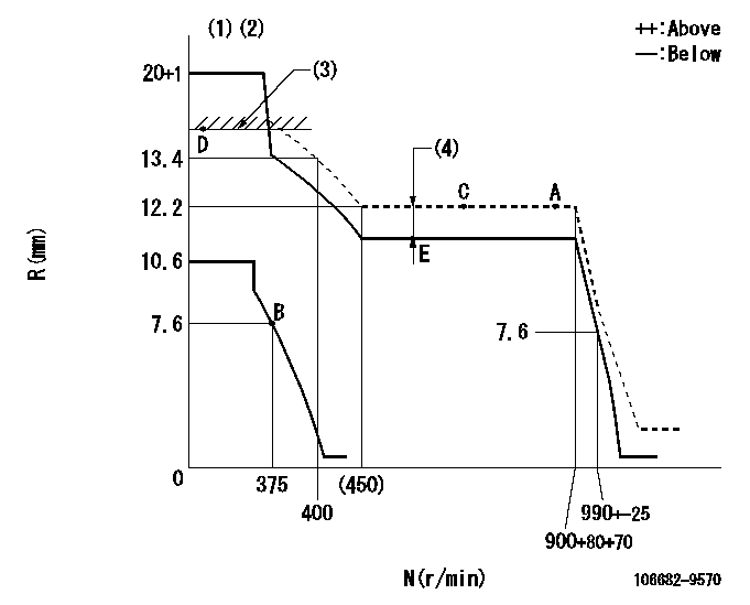
Injection quantity adjustment
Adjusting point
A
Rack position
12.2
Pump speed
r/min
900
900
900
Average injection quantity
mm3/st.
313
308
318
Max. variation between cylinders
%
0
-3
3
Basic
*
Fixing the lever
*
Boost pressure
kPa
76
76
Boost pressure
mmHg
570
570
Injection quantity adjustment_02
Adjusting point
B
Rack position
7.6+-0.5
Pump speed
r/min
375
375
375
Average injection quantity
mm3/st.
12.5
11
14
Max. variation between cylinders
%
0
-15
15
Fixing the rack
*
Boost pressure
kPa
0
0
0
Boost pressure
mmHg
0
0
0
Injection quantity adjustment_03
Adjusting point
D
Rack position
-
Pump speed
r/min
100
100
100
Average injection quantity
mm3/st.
450
440
460
Fixing the lever
*
Boost pressure
kPa
0
0
0
Boost pressure
mmHg
0
0
0
Rack limit
*
Boost compensator adjustment
Pump speed
r/min
600
600
600
Rack position
R1-2.7
Boost pressure
kPa
22.7
16
29.4
Boost pressure
mmHg
170
120
220
Boost compensator adjustment_02
Pump speed
r/min
600
600
600
Rack position
R1(12.2)
Boost pressure
kPa
66.7
64
69.4
Boost pressure
mmHg
500
480
520
Test data Ex:
Governor adjustment
N:Pump speed
R:Rack position (mm)
(1)Target notch: K
(2)Set the idle sub spring simultaneously (OUT, IN).
(3)RACK LIMIT
(4)Boost compensator stroke: BCL
----------
K=16 BCL=2.7+-0.1mm
----------
----------
K=16 BCL=2.7+-0.1mm
----------
Speed control lever angle
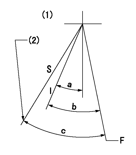
F:Full speed
I:Idle
S:Stop
(1)Confirm non-injection at speed = aa with stop lever at stop.
(2)Stopper bolt setting
----------
aa=200r/min
----------
a=20deg+-5deg b=34deg+-5deg c=45deg+-5deg
----------
aa=200r/min
----------
a=20deg+-5deg b=34deg+-5deg c=45deg+-5deg
0000001501 GOVERNOR IDLE SUB SPRING
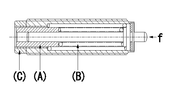
f : Installation load ON
2 stage idle sub-spring simultaneous setting method
1. (1) Remove the idling sub spring capsule from the governor.
(2)Tighten the screw (A) until it contacts the spring (B) (that is, until the set force is generated).
(3)Return to speed N1.
(4)Set so that the set force is zero.
(5)Fix using the lock nut (C).
2. Set the idle sub spring capsule adjusted as per (1) 1.
(2)Same as the normal 1 stage idle sub spring.
(3)Set so that it satisfies the governor adjustment standards.
(4)Do not loosen lock nut (C) at this time.
----------
N1=1/2
----------
----------
N1=1/2
----------
Timing setting

(1)Pump vertical direction
(2)Coupling's key groove position at No 1 cylinder's beginning of injection
(3)-
(4)-
----------
----------
a=(10deg)
----------
----------
a=(10deg)
Information:
When it is necessary to remove a component on an angle, remember that the capacity of an eyebolt is less as the angle between the supporting members and the object becomes less than 90 degrees. Eyebolts and brackets should never be bent and should only be loaded in tension.
Use a hoist to remove heavy components. Lift the engine by using an adjustable lifting beam. All supporting members (chains and cables) should be parallel to each other, and as near perpendicular as possible to the top of the object being lifted.Some removals require the use of lifting fixtures to obtain proper balance and to provide safe handling. To remove the engine ONLY, use the two lifting eyes equipped with the engine.Lifting eyes are designed for the engine arrangement as is. Alterations to lifting eyes and/or arrangement weight make the lifting devices and eyes obsolete. If you make alterations, you are responsible for providing adequate lifting devices.See your Caterpillar dealer or vessel OEM for information regarding fixtures for proper lifting of your complete engine power package.Engine and Marine Transmission Lifting
To remove the engine only or the engine and marine transmission together, use the two lifting eyes on the engine.Marine Transmission Lifting
To remove the marine transmission only, use the four permanent eyebolts in the marine transmission housing.If a component resists removal, check to be certain all nuts and bolts have been removed and that an adjacent part is not interfering.Engine Storage
These instructions give procedures and recommendations that will keep the possibility of damage at a minimum when engines are in storage for one year or less.If the engine will not be or has not been started for several weeks, the lubricating oil will drain from the cylinder walls and piston rings.If an engine remains out of service and its use is not immediately planned, special precautions should be taken. Rust can form on the cylinder liner surface, which will increase engine wear and may result in shorter engine life. To prevent this problem from becoming excessive, be sure all lubrication recommendations mentioned in the Maintenance Schedule are completed.After one year, a complete protection procedure must be followed if the engine is kept in storage longer. Refer to Storage Procedures For Caterpillar Products, SEHS9031 for more detailed information on engine storage.If freezing temperatures are expected, check the cooling system for adequate protection against freezing. A fifty/fifty solution of Caterpillar (permanent-type) Antifreeze and approved water will give protection to -29°C (-20°F).If it will be impossible to start the engine periodically, consult your Caterpillar dealer for instructions to prepare your engine for longer storage periods.If an engine remains out of service and its use is not immediately planned, special precautions should be taken. Refer to Storage Procedures For Caterpillar Products, SEHS9031 for more detailed information on engine storage.Recommendations After Engine Storage
1. Remove all outside protective covers, and any tape or grease used for protection.2. Drain the VCI oil1 and engine oil mixture from the engine. If the oil has been in the engine for
Have questions with 106682-9570?
Group cross 106682-9570 ZEXEL
Yanmar
Yanmar
Komatsu
Komatsu
Komatsu
Komatsu
106682-9570
INJECTION-PUMP ASSEMBLY