Information injection-pump assembly
ZEXEL
106682-9490
1066829490

Rating:
Cross reference number
ZEXEL
106682-9490
1066829490
Zexel num
Bosch num
Firm num
Name
106682-9490
INJECTION-PUMP ASSEMBLY
Calibration Data:
Adjustment conditions
Test oil
1404 Test oil ISO4113 or {SAEJ967d}
1404 Test oil ISO4113 or {SAEJ967d}
Test oil temperature
degC
40
40
45
Nozzle and nozzle holder
105780-8130
Bosch type code
EFEP215A
Nozzle
105780-0050
Bosch type code
DN6TD119NP1T
Nozzle holder
105780-2090
Bosch type code
EFEP215
Opening pressure
MPa
17.2
Opening pressure
kgf/cm2
175
Injection pipe
Outer diameter - inner diameter - length (mm) mm 8-3-600
Outer diameter - inner diameter - length (mm) mm 8-3-600
Overflow valve
131425-1620
Overflow valve opening pressure
kPa
255
221
289
Overflow valve opening pressure
kgf/cm2
2.6
2.25
2.95
Tester oil delivery pressure
kPa
157
157
157
Tester oil delivery pressure
kgf/cm2
1.6
1.6
1.6
Direction of rotation (viewed from drive side)
Right R
Right R
Injection timing adjustment
Direction of rotation (viewed from drive side)
Right R
Right R
Injection order
1-5-3-6-
2-4
Pre-stroke
mm
3.5
3.45
3.55
Beginning of injection position
Drive side NO.1
Drive side NO.1
Difference between angles 1
Cal 1-5 deg. 60 59.5 60.5
Cal 1-5 deg. 60 59.5 60.5
Difference between angles 2
Cal 1-3 deg. 120 119.5 120.5
Cal 1-3 deg. 120 119.5 120.5
Difference between angles 3
Cal 1-6 deg. 180 179.5 180.5
Cal 1-6 deg. 180 179.5 180.5
Difference between angles 4
Cyl.1-2 deg. 240 239.5 240.5
Cyl.1-2 deg. 240 239.5 240.5
Difference between angles 5
Cal 1-4 deg. 300 299.5 300.5
Cal 1-4 deg. 300 299.5 300.5
Injection quantity adjustment
Adjusting point
A
Rack position
14.8
Pump speed
r/min
900
900
900
Average injection quantity
mm3/st.
365
362
368
Max. variation between cylinders
%
0
-3
3
Basic
*
Fixing the rack
*
Remarks
Standard point A's rack position same as row R
Standard point A's rack position same as row R
Injection quantity adjustment_02
Adjusting point
C
Rack position
7.7+-0.5
Pump speed
r/min
400
400
400
Average injection quantity
mm3/st.
33
31.5
34.5
Max. variation between cylinders
%
0
-15
15
Fixing the rack
*
Test data Ex:
Governor adjustment
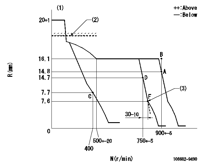
N:Pump speed
R:Rack position (mm)
(1)Target notch: K
(2)Rack limit for 106684-4022
(3)Idle sub spring setting: L1.
----------
K=13 L1=7.6-0.2mm
----------
----------
K=13 L1=7.6-0.2mm
----------
Speed control lever angle
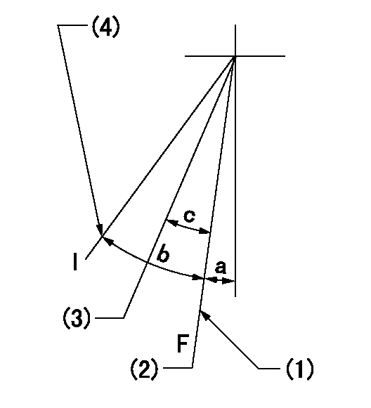
F:Full speed
I:Idle
(1)Stopper bolt setting
(2)Set the pump speed at aa. ( At delivery )
(3)Set the pump speed at bb.
(4)Stopper bolt setting
----------
aa=900r/min bb=750r/min
----------
a=16deg+-5deg b=28deg+-5deg c=8deg+-5deg
----------
aa=900r/min bb=750r/min
----------
a=16deg+-5deg b=28deg+-5deg c=8deg+-5deg
Stop lever angle

N:Pump normal
S:Stop the pump.
----------
----------
a=26.5deg+-5deg b=53deg+-5deg
----------
----------
a=26.5deg+-5deg b=53deg+-5deg
Timing setting

(1)Pump vertical direction
(2)Coupling's key groove position at No 1 cylinder's beginning of injection
(3)-
(4)-
----------
----------
a=(30deg)
----------
----------
a=(30deg)
Information:
PRESSURIZING THE SYSTEMIf the pressure isn't maintained, overflow loss can occur as cooling system temperature rises. Do not remove the cap while the system is at operating temperature. Check coolant level only when cold.If the system does not hold pressure, find the leak.Carefully inspect the radiator cap, seals, sealing surfaces and the top tank filler neck surface for damage.
RADIATOR CAPTesting The Temperature Gauge
Remember that boiling point temperature and pressure go hand-in-hand and neither one can be tested logically without considering the other. For example, the effect of pressurization and altitude on the boiling point of water is shown in the chart. If overheating and loss of coolant is a problem, a pressure loss in the system could be the cause. If an overheating condition is indicated on the temperature gauge and loss of coolant is not evident, check the accuracy of the temperature gauge. Make this check by installing a thermometer with a suitable bushing into the cylinder head.Start the engine. Partially cover the radiator to reduce air flow and cooling. The reading on the instrument panel gauge should agree with the reading on the thermometer.
Use CAUTION when working around moving parts with the engine running.
CHECKING COOLANT TEMPERATURE WITH THERMOMETERTemperature Regulators
There is a temperature regulator located at the front of each cylinder head.The opening temperature of the regulator (bench test in antmospheric pressure) should be 180 2°F (82 2°C). The regulator should be fully open at approximately 197°F (92°C). 1. Remove the regulator from the housing.2. Submerge the regulator and a thermometer in a pan of water as shown.3. Apply heat to the pan and stir the water to maintain uniformity.4. Observe the opening temperature of the regulator.If the regulator does not operate correctly, install a new one. Cooling System Hoses
Inspect all coolant hoses annually and replace if they show signs of cracking or leaking. Periodically replace all hoses, as it is many times difficult to determine the condition of a water hose by visual inspection and feel. Coolant hoses are expendable items and periodic replacement is considered good maintenance practice.Air, Gases And Steam In The System
Incomplete or improper filling is a major cause of air in the cooling system. Also, leaks in various components such as the aftercooler, and hoses allow air to enter the cooling system, especially on the inlet side of the water pump.Air in the system produces foaming or aeration and affects water pump performance. The air bubbles insulate various parts of the engine from the coolant, and hot spots form. As the air bubbles circulate or break up, coolant contacts the hot surfaces, creating steam. The steam pockets have basically the same effect as air bubbles, accelerating the formation of more steam. Consequently, coolant discharges through the overflow.Exhaust gas leakage into the system causes similar conditions. Exhaust gas can enter through internal cracks or defective cylinder head gaskets.Most of the causes can be checked by a visual inspection, while others require disassembly or a simple test.Air in the cooling system is
Have questions with 106682-9490?
Group cross 106682-9490 ZEXEL
Komatsu
Komatsu
Komatsu
Komatsu
Komatsu
Komatsu
Komatsu
106682-9490
INJECTION-PUMP ASSEMBLY