Information injection-pump assembly
ZEXEL
106682-9442
1066829442

Rating:
Cross reference number
ZEXEL
106682-9442
1066829442
Zexel num
Bosch num
Firm num
Name
106682-9442
INJECTION-PUMP ASSEMBLY
Calibration Data:
Adjustment conditions
Test oil
1404 Test oil ISO4113 or {SAEJ967d}
1404 Test oil ISO4113 or {SAEJ967d}
Test oil temperature
degC
40
40
45
Nozzle and nozzle holder
105780-8130
Bosch type code
EFEP215A
Nozzle
105780-0050
Bosch type code
DN6TD119NP1T
Nozzle holder
105780-2090
Bosch type code
EFEP215
Opening pressure
MPa
17.2
Opening pressure
kgf/cm2
175
Injection pipe
Outer diameter - inner diameter - length (mm) mm 8-4-1000
Outer diameter - inner diameter - length (mm) mm 8-4-1000
Overflow valve
131425-1620
Overflow valve opening pressure
kPa
255
221
289
Overflow valve opening pressure
kgf/cm2
2.6
2.25
2.95
Tester oil delivery pressure
kPa
157
157
157
Tester oil delivery pressure
kgf/cm2
1.6
1.6
1.6
Direction of rotation (viewed from drive side)
Left L
Left L
Injection timing adjustment
Direction of rotation (viewed from drive side)
Left L
Left L
Injection order
1-5-3-6-
2-4
Pre-stroke
mm
2.8
2.75
2.85
Beginning of injection position
Drive side NO.1
Drive side NO.1
Difference between angles 1
Cal 1-5 deg. 60 59.5 60.5
Cal 1-5 deg. 60 59.5 60.5
Difference between angles 2
Cal 1-3 deg. 120 119.5 120.5
Cal 1-3 deg. 120 119.5 120.5
Difference between angles 3
Cal 1-6 deg. 180 179.5 180.5
Cal 1-6 deg. 180 179.5 180.5
Difference between angles 4
Cyl.1-2 deg. 240 239.5 240.5
Cyl.1-2 deg. 240 239.5 240.5
Difference between angles 5
Cal 1-4 deg. 300 299.5 300.5
Cal 1-4 deg. 300 299.5 300.5
Injection quantity adjustment
Adjusting point
A
Rack position
13.9
Pump speed
r/min
900
900
900
Average injection quantity
mm3/st.
464
459
469
Max. variation between cylinders
%
0
-3
3
Basic
*
Fixing the lever
*
Boost pressure
kPa
64
64
Boost pressure
mmHg
480
480
Injection quantity adjustment_02
Adjusting point
C
Rack position
7.4+-0.5
Pump speed
r/min
315
315
315
Average injection quantity
mm3/st.
23
18
28
Max. variation between cylinders
%
0
-15
15
Fixing the rack
*
Boost pressure
kPa
0
0
0
Boost pressure
mmHg
0
0
0
Boost compensator adjustment
Pump speed
r/min
600
600
600
Rack position
R1-2.3
Boost pressure
kPa
17.3
14.6
20
Boost pressure
mmHg
130
110
150
Boost compensator adjustment_02
Pump speed
r/min
600
600
600
Rack position
R1(14.9)
Boost pressure
kPa
50.7
44
57.4
Boost pressure
mmHg
380
330
430
Test data Ex:
Governor adjustment
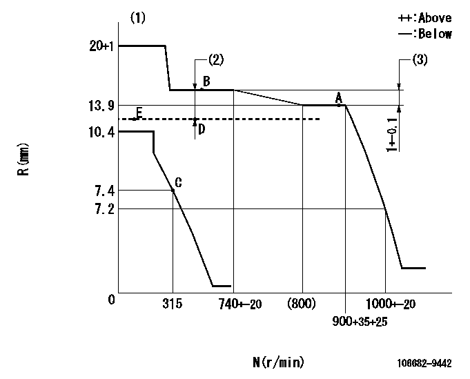
N:Pump speed
R:Rack position (mm)
(1)Target notch: K
(2)Boost compensator stroke: BCL
(3)Rack difference between N = N1 and N = N2
----------
K=8 BCL=2.3+-0.1mm N1=900r/min N2=650r/min
----------
----------
K=8 BCL=2.3+-0.1mm N1=900r/min N2=650r/min
----------
Speed control lever angle
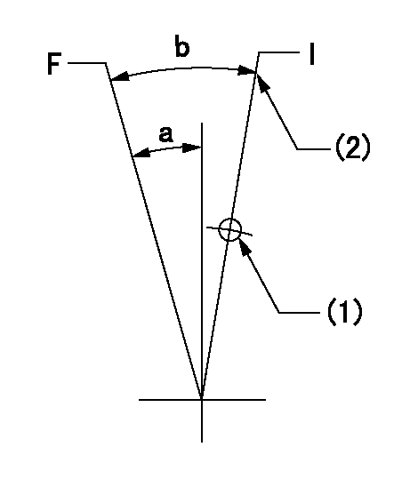
F:Full speed
I:Idle
(1)Use the hole at R = aa
(2)Stopper bolt setting
----------
aa=115mm
----------
a=8deg+-5deg b=25deg+-5deg
----------
aa=115mm
----------
a=8deg+-5deg b=25deg+-5deg
Stop lever angle
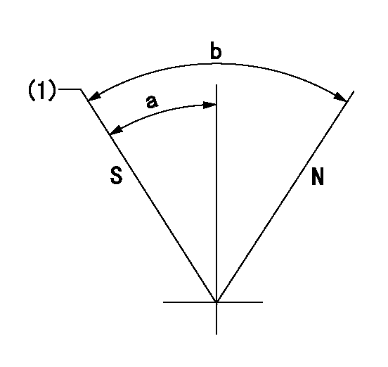
N:Pump normal
S:Stop the pump.
(1)Pump speed aa and rack position bb (to be sealed at delivery)
----------
aa=0r/min bb=1-0.5mm
----------
a=29deg+-5deg b=(73deg)
----------
aa=0r/min bb=1-0.5mm
----------
a=29deg+-5deg b=(73deg)
0000001501 LEVER
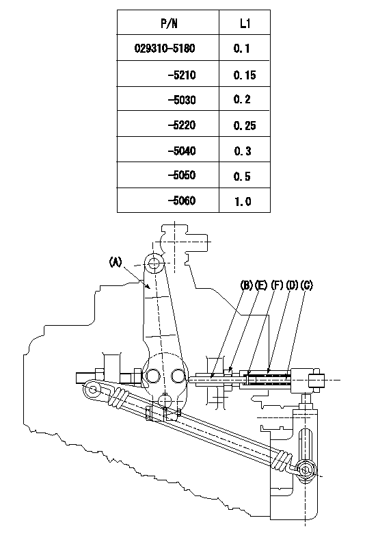
Speed lever adjustment
1. (1) For idling hold the speed lever (a) against the push rod (B).
(2)At this time, confirm that the spring (C) is not bent by the operating torque of the speed lever.
2. (1) To stop, bend the spring (C) using the speed lever.
(2)Position the rack at L2. (Adjustment is performed using the shim (F).)
(3)Set and fix using lock nut (E) so that it contacts the guide screw (D).
3. Confirm that the speed lever returns to the idling position when pulled in the stop direction and then released.
----------
L2=0.2~2mm
----------
----------
L2=0.2~2mm
----------
Timing setting

(1)Pump vertical direction
(2)Coupling's key groove position at No 1 cylinder's beginning of injection
(3)-
(4)-
----------
----------
a=(40deg)
----------
----------
a=(40deg)
Information:
Appendix
Configuration Information
Table 7
Over-Temp
Inlet Over-Temperature Alarm
Condition Expected Value
Enable Alarm Yes
Log Alarm Transitions Yes
Active Output During Alarm Output 1
Output function ON only during alarm
Assert Alarm Above
650 °C (1202 °F)
Hysteresis
20 °C (68 °F)
Upon Over Temperature extend alarm for 60 seconds
Table 8
Over-Pres
Over-Pressure Warning
Condition Expected Value
Enable Alarm Yes
Log Alarm Transitions Yes
Active Output During Alarm Output 1
Output Function ON only during alarm
Assert Alarm when the measured pressure exceeds 7" of Hg for 5% of the time during a 60 min measurement interval
Over-Pressure Alarm
Condition Expected Value
Enable Alarm Yes
Log Alarm Transitions Yes
Active Output During Alarm Output 2
Output Function Latched ON upon alarm
Assert alarm when the measured pressure exceeds 8" of Hg for 5% of the time during a 60 min measurement interval
Table 9
TC-Fail (1)
Open Thermocouple Detect
Condition Expected Value
Enable Alarm Yes
Log Alarm Transitions Yes
Output During Alarm Output 1
Output Function Latched ON upon alarm
Assert alarm if measured temperature is above
1000 °C (1832 °F)
Shorted Thermocouple Detect
Condition Expected Value
Enable Alarm Yes
Log Alarm Transitions Yes
Output During Alarm Output 1
Output Function Latched ON upon alarm
Assert alarm if pressure is greater than 1" of Hg for 10 min and measured temperature does not exceed
120 °C (248 °F)
( 1 ) Output selection applies to both open and shorted alarms
Table 10
Pressure Sensor Fail
No Change Alarm
Condition Expected Value
Enable Alarm Yes
Log Alarm Transitions Yes
Active Outputs During Alarm Output 1
Output Function Latched ON upon Alarm
Assert alarm if exhaust temperature is above
250 °C (482 °F) for 10 min and the pressure doesn't change by at least 0.25" of Hg
Negative Pressure Alarm
Condition Expected Value
Enable Alarm Yes
Log Alarm Transitions Yes
Active Output During Alarm Output 1
Output Function Latched ON during alarm
Assert Alarm if temperature is above
200 °C (392 °F) for 10 min and the pressure is less than −1" of
Have questions with 106682-9442?
Group cross 106682-9442 ZEXEL
Komatsu
Komatsu
Komatsu
Komatsu
106682-9442
INJECTION-PUMP ASSEMBLY