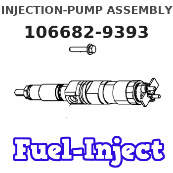
Information injection-pump assembly
BOSCH
9 400 611 281
9400611281
ZEXEL
106682-9393
1066829393
KOMATSU
6212721250
6212721250
Rating:
Service parts 106682-9393 INJECTION-PUMP ASSEMBLY:
1.
_
5.
AUTOM. ADVANCE MECHANIS
7.
COUPLING PLATE
8.
_
9.
_
11.
Nozzle and Holder
6212-12-3100
12.
Open Pre:MPa(Kqf/cm2)
24.5{250}
15.
NOZZLE SET
Include in #1:
106682-9393
as INJECTION-PUMP ASSEMBLY
Cross reference number
Zexel num
Bosch num
Firm num
Name
106682-9393
9 400 611 281
6212721250 KOMATSU
INJECTION-PUMP ASSEMBLY
SAA6D140 K 14CA INJECTION PUMP ASSY PE6P,6PD PE
SAA6D140 K 14CA INJECTION PUMP ASSY PE6P,6PD PE
Information:
Start By:a. remove valve covers 1. Loosen the fuel injection line nut at the nozzle end with tool (A).2. Loosen the fuel line nut at the fuel injection line adapter with tool (B). Remove inner fuel injection lines (1). Install caps and plugs on all fuel line openings to keep dirt out of the fuel system. If necessary, use tooling (D) to turn the engine so the valves do not make contact with the pistons when the valves are opened with tool (C) to remove the push rods.3. Put compression on the valve springs with tool (C), and remove push rods (2). Put identification marks on the push rods as to their location in the engine.4. Push the push rod end of the rocker arms down. 5. Remove the intake valve lifter with tooling (E) as follows:a. Install 5P2685 Nut (3) and 5P6601 Collet (4) on 5P2408 Outer Handle Assembly (5).b. Install 5P6599 Inner Handle Assembly (6) in 5P2408 Outer Handle Assembly (5). c. Install tooling (E) in the intake valve lifter. Hold the 5P2408 Outer Handle Assembly, and tighten the 5P6599 Inner Handle Assembly until the 5P6601 Collet is tight against the inside of the intake valve lifter. d. Remove intake valve lifters (7) from the cylinder block with tooling (E). Put identification marks on the lifters as to their location in the engine. 6. Remove the exhaust valve lifters with tooling (E) as follows:a. Install 5P2685 Nut (3) and 5P6601 Collet (4) on 5P2408 Outer Handle Assembly (5). The opening in the cylinder head assembly for the intake valve lifter is larger than the opening in the exhaust valve lifter side. The tooling and each valve lifter must be installed and removed from the intake valve lifter side.b. Install the outer handle assembly in the intake valve lifter side of the cylinder head assembly. Slide the flat area of 5P2408 Outer Handle Assembly (5) through the head casting, and install the 5P6601 Collet in the exhaust valve lifters. c. Install 5P6599 Inner Handle Assembly (6) in 5P2408 Outer Handle Assembly (5). Hold the 5P2408 Handle Assembly, and tighten the 5P6599 Handle Assembly until the 5P6601 Collet is tight against the inside of the exhaust valve lifter.d. Pull the exhaust valve lifter up until the spring on the exhaust valve lifter is free from the cylinder block.e. Remove the 5P6599 Inner Handle Assembly. Slide the 5P2408 Outer Handle Assembly through the head casting, and remove it from the intake valve lifter side of the cylinder head. f. Use a magnet, and remove exhaust valve lifters (8) from the intake valve lifter side of the cylinder head assembly. Put identification marks on the lifters as to their location in the engine.7. Remove the guide springs from the lifters.Install Valve Lifters
Steps 1 and 2 must be done to install intake or exhaust valve lifters.
Make sure guide spring (9) is not damaged or worn. If the guide spring is damaged or worn, replace the guide spring. See Guideline For Reusable
Steps 1 and 2 must be done to install intake or exhaust valve lifters.
Make sure guide spring (9) is not damaged or worn. If the guide spring is damaged or worn, replace the guide spring. See Guideline For Reusable
Have questions with 106682-9393?
Group cross 106682-9393 ZEXEL
Komatsu
Komatsu
Komatsu
Komatsu
Komatsu
Komatsu
Komatsu
Komatsu
Komatsu
106682-9393
9 400 611 281
6212721250
INJECTION-PUMP ASSEMBLY
SAA6D140
SAA6D140