Information injection-pump assembly
ZEXEL
106682-9371
1066829371
KOMATSU
6215711690
6215711690
Rating:
Service parts 106682-9371 INJECTION-PUMP ASSEMBLY:
1.
_
5.
AUTOM. ADVANCE MECHANIS
7.
COUPLING PLATE
8.
_
9.
_
11.
Nozzle and Holder
6215-11-3300
12.
Open Pre:MPa(Kqf/cm2)
24.5{250}
15.
NOZZLE SET
Include in #1:
106682-9371
as INJECTION-PUMP ASSEMBLY
Cross reference number
ZEXEL
106682-9371
1066829371
KOMATSU
6215711690
6215711690
Zexel num
Bosch num
Firm num
Name
Calibration Data:
Adjustment conditions
Test oil
1404 Test oil ISO4113 or {SAEJ967d}
1404 Test oil ISO4113 or {SAEJ967d}
Test oil temperature
degC
40
40
45
Nozzle and nozzle holder
105780-8130
Bosch type code
EFEP215A
Nozzle
105780-0050
Bosch type code
DN6TD119NP1T
Nozzle holder
105780-2090
Bosch type code
EFEP215
Opening pressure
MPa
17.2
Opening pressure
kgf/cm2
175
Injection pipe
Outer diameter - inner diameter - length (mm) mm 8-3-600
Outer diameter - inner diameter - length (mm) mm 8-3-600
Overflow valve
131425-1620
Overflow valve opening pressure
kPa
255
221
289
Overflow valve opening pressure
kgf/cm2
2.6
2.25
2.95
Tester oil delivery pressure
kPa
157
157
157
Tester oil delivery pressure
kgf/cm2
1.6
1.6
1.6
Direction of rotation (viewed from drive side)
Right R
Right R
Injection timing adjustment
Direction of rotation (viewed from drive side)
Right R
Right R
Injection order
1-5-3-6-
2-4
Pre-stroke
mm
3
2.95
3.05
Beginning of injection position
Drive side NO.1
Drive side NO.1
Difference between angles 1
Cal 1-5 deg. 60 59.5 60.5
Cal 1-5 deg. 60 59.5 60.5
Difference between angles 2
Cal 1-3 deg. 120 119.5 120.5
Cal 1-3 deg. 120 119.5 120.5
Difference between angles 3
Cal 1-6 deg. 180 179.5 180.5
Cal 1-6 deg. 180 179.5 180.5
Difference between angles 4
Cyl.1-2 deg. 240 239.5 240.5
Cyl.1-2 deg. 240 239.5 240.5
Difference between angles 5
Cal 1-4 deg. 300 299.5 300.5
Cal 1-4 deg. 300 299.5 300.5
Injection quantity adjustment
Adjusting point
A
Rack position
15.5
Pump speed
r/min
600
600
600
Average injection quantity
mm3/st.
372
369
375
Max. variation between cylinders
%
0
-3
3
Basic
*
Fixing the rack
*
Remarks
Standard point A's rack position same as row R
Standard point A's rack position same as row R
Injection quantity adjustment_02
Adjusting point
C
Rack position
7.9+-0.5
Pump speed
r/min
400
400
400
Average injection quantity
mm3/st.
28.5
27
30
Max. variation between cylinders
%
0
-15
15
Fixing the rack
*
Test data Ex:
Governor adjustment
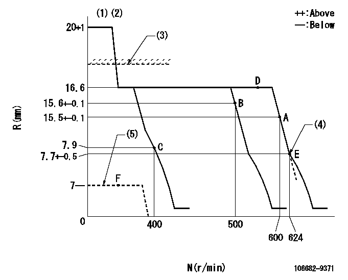
N:Pump speed
R:Rack position (mm)
(1)Target notch: K
(2)Tolerance for racks not indicated: +-0.05mm.
(3)RACK LIMIT for 106684-4242
(4)Idle sub spring setting: L1.
(5)Stop lever at stopping (with the stop lever at full)
----------
K=11 L1=7.7-0.2mm
----------
----------
K=11 L1=7.7-0.2mm
----------
Speed control lever angle
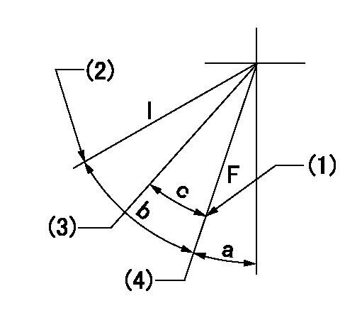
F:Full speed
I:Idle
(1)Stopper bolt setting
(2)Stopper bolt setting
(3)Set the pump speed at aa
(4)Set the pump speed at bb (at delivery)
----------
aa=500r/min bb=600r/min
----------
a=22deg+-5deg b=15deg+-5deg c=7deg+-5deg
----------
aa=500r/min bb=600r/min
----------
a=22deg+-5deg b=15deg+-5deg c=7deg+-5deg
Stop lever angle

N:Pump normal
S:Stop the pump.
----------
----------
a=26.5deg+-5deg b=53deg+-5deg
----------
----------
a=26.5deg+-5deg b=53deg+-5deg
Timing setting

(1)Pump vertical direction
(2)Coupling's key groove position at No 1 cylinder's beginning of injection
(3)-
(4)-
----------
----------
a=(20deg)
----------
----------
a=(20deg)
Information:
1. Remove the two bolts, and remove the fuel ratio control from the governor. Remove O-ring seal (1) from the fuel ratio control. 2. Put tooling (A) in a vise as shown so that the station being used is not over the vise jaw. Place the fuel ratio control over the pins in tooling (A). Remove cover (2) and the O-ring from fuel ratio control.
There is spring force behind cover (3). Hold cover (3) in position, and slowly remove the bolts that hold it to release the spring force.
3. Remove cover (3) from housing (4). 4. Remove spring (7), washer (5), and diaphragm (8) from retainer (6). Remove retainer (6) from housing (9). 5. Remove nut (14) from extension (13), and remove the extension from retainer (6). Remove valve (10), spring (11) and O-ring seal (12) from the extension. 6. Remove spring (16), retainer (15) and spring (17) from the housing. 7. Remove piston assembly (18) from the housing. 8. Use tooling (B), and remove snap ring (19) and the wave washers from valve assembly (20). Remove piston assembly (21) from the valve assembly.9. Remove seal (22) from piston (21). 10. Clean and inspect all parts. Make a replacement of all parts that are worn or damaged.Assemble Fuel Ratio Control
1. If valve (1) and stem (2) are loosened or partially unscrewed, the valve assembly should be replaced with new. 2. Put seal (4) on piston (3), and put piston (3) on valve assembly (5). 3. Put two wave washers in position on valve (5), and use tooling (A) to install the snap ring on the valve assembly. 4. Place housing (7) on tooling (B), and put tooling (C) into the bore of the housing. Lubricate tooling (C) with clean engine oil.5. Put a small amount of clean oil on the seal of the piston assembly, and push piston assembly (6) into position with a smooth swift motion. 6. Place spring (8) and retainer and spring (9) in position in housing (7). 7. Put O-ring seal (12) on extension (13). Put spring (11) and valve (10) in position on the extension.8. Lubricate O-ring seal (12) with clean engine oil. Install extension (13) in retainer (14). Install nut (15). 9. Put diaphragm (18), washer (17) and spring (16) in position on retainer (14). Install retainer (14) in housing (7). 10. Hold retainer (14) in position, and install cover (19) on the housing. Install the bolts that hold the cover, and tighten them to a torque of 9 3 N m (7 2 lb ft). 11. Inspect the O-ring for cover (20). Replace the O-ring if worn or broken. Install the cover. 12. Put O-ring seal (21) in position on the fuel ratio control.13. Put the fuel ratio control in position on the governor. Make sure the flange on the end of the fuel ratio control is behind the groove (slot) in the lever. Install the bolts that hold the fuel ratio control in position. See the Testing