Information injection-pump assembly
ZEXEL
106682-9370
1066829370
Rating:
Service parts 106682-9370 INJECTION-PUMP ASSEMBLY:
1.
_
5.
AUTOM. ADVANCE MECHANIS
7.
COUPLING PLATE
8.
_
9.
_
11.
Nozzle and Holder
6215-11-3300
12.
Open Pre:MPa(Kqf/cm2)
24.5{250}
15.
NOZZLE SET
Include in #1:
106682-9370
as INJECTION-PUMP ASSEMBLY
Cross reference number
ZEXEL
106682-9370
1066829370
Zexel num
Bosch num
Firm num
Name
106682-9370
INJECTION-PUMP ASSEMBLY
Calibration Data:
Adjustment conditions
Test oil
1404 Test oil ISO4113 or {SAEJ967d}
1404 Test oil ISO4113 or {SAEJ967d}
Test oil temperature
degC
40
40
45
Nozzle and nozzle holder
105780-8130
Bosch type code
EFEP215A
Nozzle
105780-0050
Bosch type code
DN6TD119NP1T
Nozzle holder
105780-2090
Bosch type code
EFEP215
Opening pressure
MPa
17.2
Opening pressure
kgf/cm2
175
Injection pipe
Outer diameter - inner diameter - length (mm) mm 8-3-600
Outer diameter - inner diameter - length (mm) mm 8-3-600
Overflow valve
131424-7120
Overflow valve opening pressure
kPa
255
221
289
Overflow valve opening pressure
kgf/cm2
2.6
2.25
2.95
Tester oil delivery pressure
kPa
157
157
157
Tester oil delivery pressure
kgf/cm2
1.6
1.6
1.6
Direction of rotation (viewed from drive side)
Right R
Right R
Injection timing adjustment
Direction of rotation (viewed from drive side)
Right R
Right R
Injection order
1-5-3-6-
2-4
Pre-stroke
mm
3
2.95
3.05
Beginning of injection position
Drive side NO.1
Drive side NO.1
Difference between angles 1
Cal 1-5 deg. 60 59.5 60.5
Cal 1-5 deg. 60 59.5 60.5
Difference between angles 2
Cal 1-3 deg. 120 119.5 120.5
Cal 1-3 deg. 120 119.5 120.5
Difference between angles 3
Cal 1-6 deg. 180 179.5 180.5
Cal 1-6 deg. 180 179.5 180.5
Difference between angles 4
Cyl.1-2 deg. 240 239.5 240.5
Cyl.1-2 deg. 240 239.5 240.5
Difference between angles 5
Cal 1-4 deg. 300 299.5 300.5
Cal 1-4 deg. 300 299.5 300.5
Injection quantity adjustment
Adjusting point
A
Rack position
13.5
Pump speed
r/min
600
600
600
Average injection quantity
mm3/st.
372
369
375
Max. variation between cylinders
%
0
-3
3
Basic
*
Fixing the rack
*
Remarks
Standard point A's rack position same as row R
Standard point A's rack position same as row R
Injection quantity adjustment_02
Adjusting point
C
Rack position
5.6+-0.5
Pump speed
r/min
400
400
400
Average injection quantity
mm3/st.
28.5
27
30
Max. variation between cylinders
%
0
-15
15
Fixing the rack
*
Test data Ex:
Governor adjustment
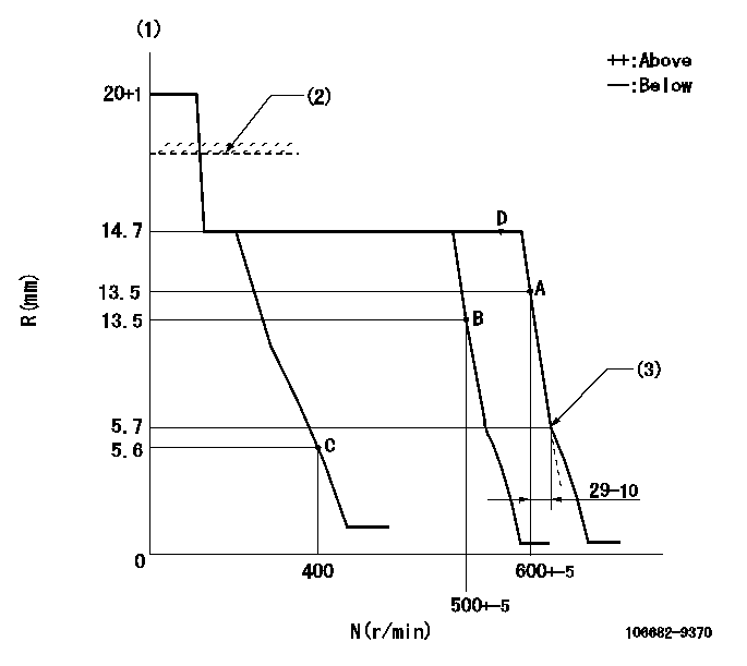
N:Pump speed
R:Rack position (mm)
(1)Target notch: K
(2)RACK LIMIT for 106684-4220; RAL
(3)Set idle sub-spring
----------
K=15 RAL=15.2+0.2mm
----------
----------
K=15 RAL=15.2+0.2mm
----------
Speed control lever angle
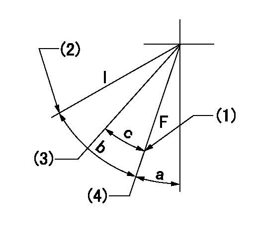
F:Full speed
I:Idle
(1)Stopper bolt setting
(2)Stopper bolt setting
(3)Set the pump speed at aa
(4)Set the pump speed at bb (at delivery)
----------
aa=500r/min bb=600r/min
----------
a=23deg+-5deg b=14deg+-5deg c=7deg+-5deg
----------
aa=500r/min bb=600r/min
----------
a=23deg+-5deg b=14deg+-5deg c=7deg+-5deg
Stop lever angle
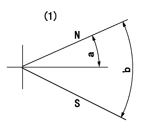
N:Pump normal
S:Stop the pump.
(1)Confirm non-injection with stop lever at N = aa at stop.
----------
aa=100r/min
----------
a=26.5deg+-5deg b=53deg+-5deg
----------
aa=100r/min
----------
a=26.5deg+-5deg b=53deg+-5deg
Timing setting

(1)Pump vertical direction
(2)Coupling's key groove position at No 1 cylinder's beginning of injection
(3)-
(4)-
----------
----------
a=(20deg)
----------
----------
a=(20deg)
Information:
1. Remove fuel line (1) from the fuel transfer pump.2. Put caps in the fuel line openings to prevent fuel system contamination.3. Remove bolts (2), and remove fuel transfer pump (3). Check the condition of the O-ring seal on the fuel transfer pump. If necessary, make a replacement.Install Fuel Transfer Pump
1. Be sure O-ring seal (1) is in position on the fuel transfer pump. Put clean engine oil on the O-ring seal.2. Put fuel transfer pump (2) in position, and install the bolts that hold it in place.3. Remove the caps from the fuel line openings, and install fuel line (3).4. Prime the fuel system. See the Maintenance Guide for this procedure.Disassemble Fuel Transfer Pump
Start By:a. remove fuel transfer pump 1. Remove seal (1) from the fuel transfer pump.
Cover (2) is under spring tension. Remove the bolts that hold cover (2) slowly to prevent injury.
2. Remove bolts (3) and cover (2) from the housing. 3. Remove seals (4) and valve (5) from cover (2). 4. Remove spring (6) from the piston.
Mark the orientation of valve (8) as to its location in the housing.
5. Remove washer (7), valve (8) and the seal from the housing. 6. Remove piston (9) and sleeve (10) from the housing. 7. Remove seal (11) from sleeve (12). 8. Remove guide and tappet assembly (13) from the housing. 9. Remove seal (14) from guide (15).
If tappet (17) or the guide are damaged or worn, they must be replaced as a unit.
10. Remove ring (16) from tappet (17) and the tappet from guide (15). 11. Remove the bolts and cover (18) from the housing. 12. Remove seal (19) from cover (18). 13. Remove valve (20) from the housing if necessary. Assemble Fuel Transfer Pump
1. Install valve (2) in housing (1) as shown. 2. Put clean fuel on seal (4), and install it on cover (3).3. Install cover (3) on the housing.
The tappet and guide must be serviced as a unit.
4. Install tappet (6) in guide (5). Install ring (7) on tappet (6) to hold the tappet in the guide. 5. Put clean fuel on seal (8), and install it on guide and tappet assembly (9).6. Install guide and tappet assembly (9) in the housing as shown. 7. Put clean fuel on seal (10), and install it on sleeve (11).8. Install sleeve (11) in the housing. 9. Install piston (12) in the housing. 10. Install seal valve (14) and washer (13) in the housing as shown. Be sure valve (14) is the correct position in the housing. 11. Install spring (15) in the piston. 12. Install valve (18) in cover (16) as shown.13. Put clean fuel on seals (17), and put them in position on cover (16).14. Install cover (16) on the housing. 15. Put seal (19) in position on the fuel transfer pump.16. Install the fuel transfer pump on the fuel injection pump housing.End By:a. install fuel transfer pump
Have questions with 106682-9370?
Group cross 106682-9370 ZEXEL
106682-9370
INJECTION-PUMP ASSEMBLY