Information injection-pump assembly
BOSCH
9 400 619 872
9400619872
ZEXEL
106682-9340
1066829340
KOMATSU
6212711340
6212711340
Rating:
Service parts 106682-9340 INJECTION-PUMP ASSEMBLY:
1.
_
5.
AUTOM. ADVANCE MECHANIS
7.
COUPLING PLATE
8.
_
9.
_
11.
Nozzle and Holder
12.
Open Pre:MPa(Kqf/cm2)
24.5{250}
15.
NOZZLE SET
Include in #1:
106682-9340
as INJECTION-PUMP ASSEMBLY
Cross reference number
BOSCH
9 400 619 872
9400619872
ZEXEL
106682-9340
1066829340
KOMATSU
6212711340
6212711340
Zexel num
Bosch num
Firm num
Name
Calibration Data:
Adjustment conditions
Test oil
1404 Test oil ISO4113 or {SAEJ967d}
1404 Test oil ISO4113 or {SAEJ967d}
Test oil temperature
degC
40
40
45
Nozzle and nozzle holder
105780-8130
Bosch type code
EFEP215A
Nozzle
105780-0050
Bosch type code
DN6TD119NP1T
Nozzle holder
105780-2090
Bosch type code
EFEP215
Opening pressure
MPa
17.2
Opening pressure
kgf/cm2
175
Injection pipe
Outer diameter - inner diameter - length (mm) mm 8-4-1000
Outer diameter - inner diameter - length (mm) mm 8-4-1000
Overflow valve
131424-3420
Overflow valve opening pressure
kPa
255
221
289
Overflow valve opening pressure
kgf/cm2
2.6
2.25
2.95
Tester oil delivery pressure
kPa
157
157
157
Tester oil delivery pressure
kgf/cm2
1.6
1.6
1.6
Direction of rotation (viewed from drive side)
Right R
Right R
Injection timing adjustment
Direction of rotation (viewed from drive side)
Right R
Right R
Injection order
1-5-3-6-
2-4
Pre-stroke
mm
3
2.95
3.05
Beginning of injection position
Drive side NO.1
Drive side NO.1
Difference between angles 1
Cal 1-5 deg. 60 59.5 60.5
Cal 1-5 deg. 60 59.5 60.5
Difference between angles 2
Cal 1-3 deg. 120 119.5 120.5
Cal 1-3 deg. 120 119.5 120.5
Difference between angles 3
Cal 1-6 deg. 180 179.5 180.5
Cal 1-6 deg. 180 179.5 180.5
Difference between angles 4
Cyl.1-2 deg. 240 239.5 240.5
Cyl.1-2 deg. 240 239.5 240.5
Difference between angles 5
Cal 1-4 deg. 300 299.5 300.5
Cal 1-4 deg. 300 299.5 300.5
Injection quantity adjustment
Adjusting point
A
Rack position
13.5
Pump speed
r/min
600
600
600
Average injection quantity
mm3/st.
371
368
374
Max. variation between cylinders
%
0
-3
3
Basic
*
Fixing the rack
*
Injection quantity adjustment_02
Adjusting point
C
Rack position
5.6+-0.5
Pump speed
r/min
400
400
400
Average injection quantity
mm3/st.
13
11.5
14.5
Max. variation between cylinders
%
0
-15
15
Fixing the rack
*
Injection quantity adjustment_03
Adjusting point
E
Rack position
-
Pump speed
r/min
100
100
100
Average injection quantity
mm3/st.
380
370
390
Fixing the lever
*
Rack limit
*
Test data Ex:
Governor adjustment
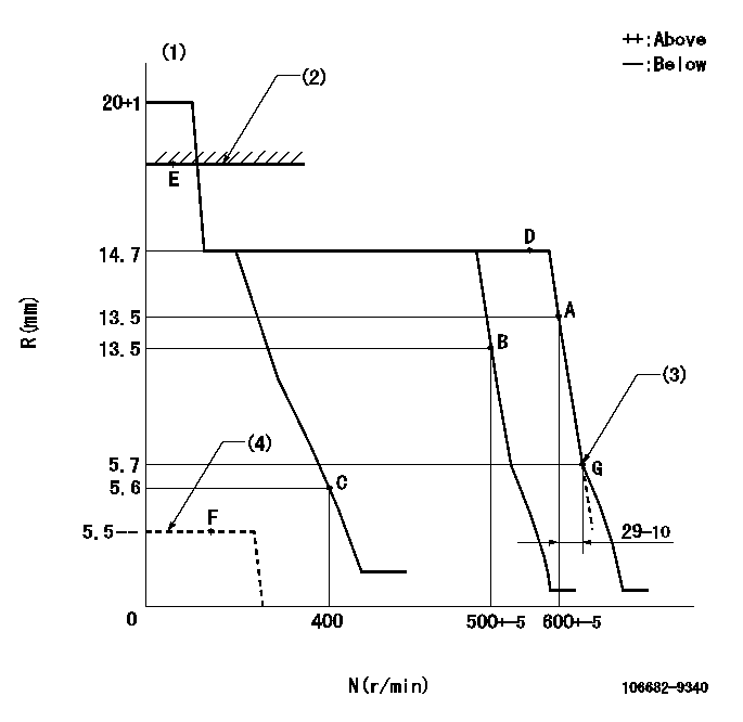
N:Pump speed
R:Rack position (mm)
(1)Target notch: K
(2)RACK LIMIT: RAL
(3)Set idle sub-spring
(4)Stop lever at stopping (with the stop lever at full)
----------
K=15 RAL=15.2+0.2mm
----------
----------
K=15 RAL=15.2+0.2mm
----------
Speed control lever angle
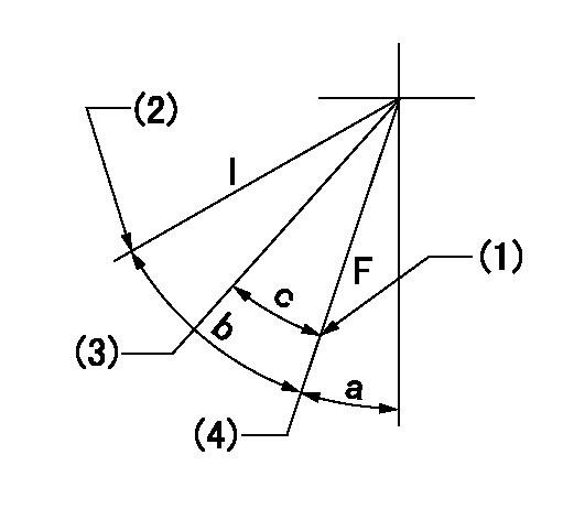
F:Full speed
I:Idle
(1)Stopper bolt setting
(2)Stopper bolt setting
(3)Set the pump speed at aa
(4)Set the pump speed at bb (at delivery)
----------
aa=500r/min bb=600r/min
----------
a=2deg+-5deg b=14deg+-5deg c=7deg+-5deg
----------
aa=500r/min bb=600r/min
----------
a=2deg+-5deg b=14deg+-5deg c=7deg+-5deg
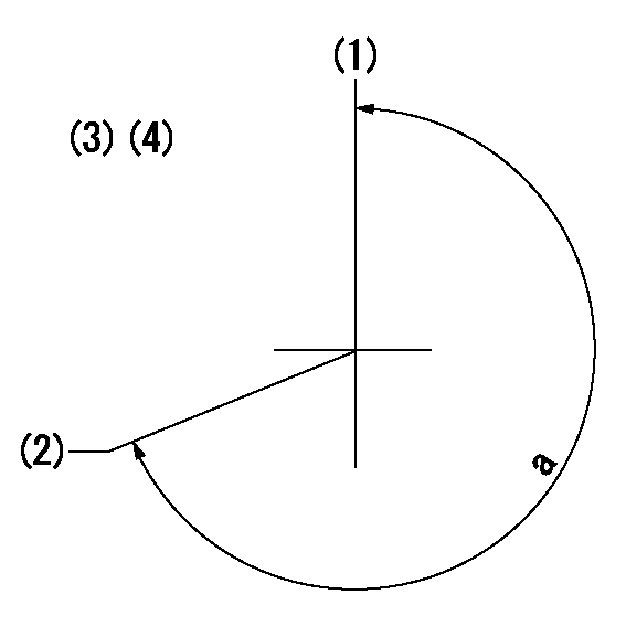
Stop lever angle

N:Pump normal
S:Stop the pump.
----------
----------
a=26.5deg+-5deg b=53deg+-5deg
----------
----------
a=26.5deg+-5deg b=53deg+-5deg
Timing setting
(1)Pump vertical direction
(2)Coupling's key groove position at No 1 cylinder's beginning of injection
(3)-
(4)-
----------
----------
a=(260deg)
----------
----------
a=(260deg)
Information:
The problems in this section are problems that do come about and are normally called "low power". These problems are not necessarily more common than engine problems, but they are possible problems which you need to read and check before an engine is disassembled.Read all of the items but make sure the first three are checked completely before making any engine test.Possible Causes/Corrections
Tachometer Error
To check, connect a tachometer of known accuracy to the engine. Run the engine and make a comparison of the readings of the vehicle and test tachometers. If vehicle tachometer is defective, make repairs as necessary or install a new tachometer.Engine Operated At High Altitude
Less oxygen at higher altitudes causes the engine horsepower to go down. There is no effect on the horsepower of the engine for the first 2280 m (7500 ft) above sea level of operation.Brakes Do Not Completely Release
Check the brakes by feeling all the brake drums. If the brakes of a wheel do not completely release, the brake drum for that wheel will be hotter than the brake drums for the other wheels. With the truck lifted with a jack, the wheels must have free rotation when turned by hand.Extra Engine Driven Equipment
Air compressors, hydraulic pumps, alternator, and other engine driven equipment that has damage, or that was not installed correctly, or that is not in correct adjustment, can take more horsepower to drive than expected. If necessary, disconnect the equipment and test the engine.Speedometer Error
A defective speedometer does not give the correct speed or the correct indication of fuel consumption. An indication of low speed can cause the operator to feel that he has a power problem.Speeds Too High
The need for more horsepower is easy to see as the speed of the vehicle is increased. This is especially true if the front of the vehicle has a large surface area. Application personnel can give you the horsepower necessary for different vehicle designs at different speeds.Overload On Vehicle
Application personnel can give you the horsepower needs for different vehicles.High Moving Resistance
Soft ground conditions cause a need for more horsepower. To see if the problem is the engine, test the vehicle on a surface known to be good, or test on a chassis dynamometer.High Wind Resistance
The horsepower needs for a truck can be divided into two parts. Part of the horsepower is used to move the vehicle and part is used to get through the resistance of the wind. The horsepower necessary to get through the resistance of the wind will increase as the vehicle is used at higher speeds. Vehicles with a large front area have a higher wind resistance and take more horsepower than those with a small front area. Some types of trucks, for example those used for the transportation of automobiles and or boats have high wind resistance even if the front area is small. Moving against the wind has the same effect on wind resistance as does higher vehicle speed.Power Loss In Drive Gears
It is possible for a