Information injection-pump assembly
BOSCH
9 400 610 975
9400610975
ZEXEL
106682-9291
1066829291
KOMATSU
6162732370
6162732370
Rating:
Service parts 106682-9291 INJECTION-PUMP ASSEMBLY:
1.
_
5.
AUTOM. ADVANCE MECHANIS
7.
COUPLING PLATE
8.
_
9.
_
11.
Nozzle and Holder
6162-13-3702
12.
Open Pre:MPa(Kqf/cm2)
26.0{265}
15.
NOZZLE SET
Include in #1:
106682-9291
as INJECTION-PUMP ASSEMBLY
Cross reference number
BOSCH
9 400 610 975
9400610975
ZEXEL
106682-9291
1066829291
KOMATSU
6162732370
6162732370
Zexel num
Bosch num
Firm num
Name
106682-9291
9 400 610 975
6162732370 KOMATSU
INJECTION-PUMP ASSEMBLY
SA6D170 K 14CA INJECTION PUMP ASSY PE6P,6PD PE
SA6D170 K 14CA INJECTION PUMP ASSY PE6P,6PD PE
Calibration Data:
Adjustment conditions
Test oil
1404 Test oil ISO4113 or {SAEJ967d}
1404 Test oil ISO4113 or {SAEJ967d}
Test oil temperature
degC
40
40
45
Nozzle and nozzle holder
105780-8130
Bosch type code
EFEP215A
Nozzle
105780-0050
Bosch type code
DN6TD119NP1T
Nozzle holder
105780-2090
Bosch type code
EFEP215
Opening pressure
MPa
17.2
Opening pressure
kgf/cm2
175
Injection pipe
Outer diameter - inner diameter - length (mm) mm 8-4-1000
Outer diameter - inner diameter - length (mm) mm 8-4-1000
Overflow valve
131425-1620
Overflow valve opening pressure
kPa
255
221
289
Overflow valve opening pressure
kgf/cm2
2.6
2.25
2.95
Tester oil delivery pressure
kPa
157
157
157
Tester oil delivery pressure
kgf/cm2
1.6
1.6
1.6
Direction of rotation (viewed from drive side)
Left L
Left L
Injection timing adjustment
Direction of rotation (viewed from drive side)
Left L
Left L
Injection order
1-5-3-6-
2-4
Pre-stroke
mm
3.2
3.15
3.25
Beginning of injection position
Drive side NO.1
Drive side NO.1
Difference between angles 1
Cal 1-5 deg. 60 59.5 60.5
Cal 1-5 deg. 60 59.5 60.5
Difference between angles 2
Cal 1-3 deg. 120 119.5 120.5
Cal 1-3 deg. 120 119.5 120.5
Difference between angles 3
Cal 1-6 deg. 180 179.5 180.5
Cal 1-6 deg. 180 179.5 180.5
Difference between angles 4
Cyl.1-2 deg. 240 239.5 240.5
Cyl.1-2 deg. 240 239.5 240.5
Difference between angles 5
Cal 1-4 deg. 300 299.5 300.5
Cal 1-4 deg. 300 299.5 300.5
Injection quantity adjustment
Adjusting point
A
Rack position
16.6
Pump speed
r/min
875
875
875
Average injection quantity
mm3/st.
425
421
429
Max. variation between cylinders
%
0
-3
3
Basic
*
Fixing the lever
*
Boost pressure
kPa
57.3
57.3
Boost pressure
mmHg
430
430
Injection quantity adjustment_02
Adjusting point
B
Rack position
6.9+-0.5
Pump speed
r/min
335
335
335
Average injection quantity
mm3/st.
21
16
26
Max. variation between cylinders
%
0
-15
15
Fixing the rack
*
Boost pressure
kPa
0
0
0
Boost pressure
mmHg
0
0
0
Injection quantity adjustment_03
Adjusting point
E
Rack position
-
Pump speed
r/min
100
100
100
Average injection quantity
mm3/st.
410
410
430
Fixing the lever
*
Boost pressure
kPa
0
0
0
Boost pressure
mmHg
0
0
0
Rack limit
*
Boost compensator adjustment
Pump speed
r/min
500
500
500
Rack position
14.6
Boost pressure
kPa
9.3
6.6
12
Boost pressure
mmHg
70
50
90
Boost compensator adjustment_02
Pump speed
r/min
500
500
500
Rack position
17.8
Boost pressure
kPa
44
37.3
50.7
Boost pressure
mmHg
330
280
380
Test data Ex:
Governor adjustment
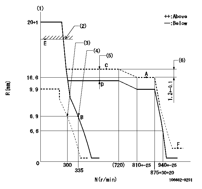
N:Pump speed
R:Rack position (mm)
(1)Target notch: K
(2)RACK LIMIT
(3)Set idle sub-spring
(4)Main spring setting
(5)Boost compensator stroke: BCL
(6)Rack difference between N = N1 and N = N2
----------
K=5 BCL=3.2+-0.1mm N1=875r/min N2=650r/min
----------
----------
K=5 BCL=3.2+-0.1mm N1=875r/min N2=650r/min
----------
Speed control lever angle
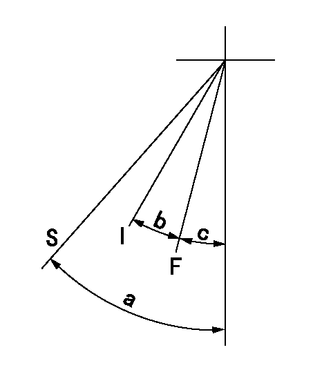
F:Full speed
I:Idle
S:Stop
----------
----------
a=52deg+-5deg b=(24deg)+-5deg c=(15deg)+-5deg
----------
----------
a=52deg+-5deg b=(24deg)+-5deg c=(15deg)+-5deg
0000001501 LEVER
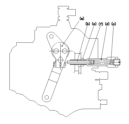
1. Adjustment of the control lever
(1)Perform idling with the speed lever (a) contacting the pushrod (b) At this time, confirm that the spring (c) is not compressed by speed lever (a)'s operating torque.
(2)To set the stop position, compress spring (c) using the speed lever (a) and adjust the rack so that it contacts the guide screw at position L1. Then, set and fix using the lock nut (e).
Adjust rack position at this time using shim (f).
(3)After pulling the speed lever (a) in the stop direction and releasing it, confirm that it returns to the idle position.
----------
L1=0.2~2mm
----------
----------
L1=0.2~2mm
----------
Timing setting

(1)Pump vertical direction
(2)Coupling's key groove position at No 1 cylinder's beginning of injection
(3)-
(4)-
----------
----------
a=(30deg)
----------
----------
a=(30deg)
Information:
Start By:a. remove oil pumpb. remove oil pan plate
Keep all parts clean from contaminants. Contaminants put into the system may cause rapid wear and shortened component life.
1. Remove No. 1, 3, 5 and 7 main bearing caps (1). Remove the lower halves of the main bearings from the main bearing caps.
If the crankshaft is turned in the wrong direction, the tab on the bearing will be pushed between the crankshaft and the bearing area in the cylinder block. This can result in damage to the cylinder block and/or the crankshaft.
2. Install tool (A) in the hole in the crankshaft journal, and turn the crankshaft to remove the upper halves of main bearings (2).3. Remove crankshaft thrust bearings (3). Install the main bearings dry when the clearance checks are made. Put clean engine oil on the main bearings for final assembly.
Make sure the upper and lower halves of the main bearings are installed so the bearing tabs fit into the notch in the cylinder block and the main bearing caps.
4. Use tool (A), and install new upper halves of main bearings (2) in the cylinder block. Install new lower halves of main bearings (2) in main bearing caps (1).
When the bearing clearance is checked and the engine is in an upright position (vertical position with cylinder head on top), the crankshaft will have to be lifted up and held against the upper halves of the main bearings to get a correct measurement with the Plastigage. The Plastigage will not hold the weight of the crankshaft and give a correct indication. If the engine is in a horizontal position, it is not necessary to hold the crankshaft up. Do not turn the crankshaft when the Plastigage is in position to check clearances.
For complete details concerning measuring bearing clearances, see Engine Bearings And Crankshafts, Form No. SEBD0531.5. Check the main bearing clearance with Plastigage (B) as follows:a. Put a piece of Plastigage (B) on the crankshaft journals as shown.
Make sure the part number on the main bearing cap is toward the front of the engine and the number on the main bearing cap is the same as the number on the cylinder block on the left side of each main bearing cap.
b. Put main bearing caps (1) in position in the engine. Put 2P2506 Thread Lubricant on the bolt threads and the face of the washers, and install the bolts. Tighten the bolts to a torque of 40 4 N m (30 3 lb ft).c. Put a mark on each bolt and main bearing cap; then tighten the bolts 90° more.d. Remove the main bearing caps, and measure the Plastigage to find the bearing clearance. The main bearing clearance for new bearings must be 0.076 to 0.165 mm (.0030 to .0065 in). Maximum permissible clearance with used bearings is 0.25 mm (.010 in). 6. Put clean oil on the thrust bearing, and install a new thrust bearing for the rear main bearing. Install the thrust bearing with the identification
Have questions with 106682-9291?
Group cross 106682-9291 ZEXEL
Komatsu
Komatsu
Komatsu
Komatsu
Komatsu
Komatsu
Komatsu
106682-9291
9 400 610 975
6162732370
INJECTION-PUMP ASSEMBLY
SA6D170
SA6D170