Information injection-pump assembly
BOSCH
9 400 613 392
9400613392
ZEXEL
106682-9264
1066829264
KOMATSU
6215711810
6215711810
Rating:
Service parts 106682-9264 INJECTION-PUMP ASSEMBLY:
1.
_
5.
AUTOM. ADVANCE MECHANIS
7.
COUPLING PLATE
8.
_
9.
_
11.
Nozzle and Holder
12.
Open Pre:MPa(Kqf/cm2)
24.5{250}
15.
NOZZLE SET
Include in #1:
106682-9264
as INJECTION-PUMP ASSEMBLY
Cross reference number
BOSCH
9 400 613 392
9400613392
ZEXEL
106682-9264
1066829264
KOMATSU
6215711810
6215711810
Zexel num
Bosch num
Firm num
Name
9 400 613 392
6215711810 KOMATSU
INJECTION-PUMP ASSEMBLY
SA12V140 * K 14CA PE6P,6PD PE
SA12V140 * K 14CA PE6P,6PD PE
Calibration Data:
Adjustment conditions
Test oil
1404 Test oil ISO4113 or {SAEJ967d}
1404 Test oil ISO4113 or {SAEJ967d}
Test oil temperature
degC
40
40
45
Nozzle and nozzle holder
105780-8130
Bosch type code
EFEP215A
Nozzle
105780-0050
Bosch type code
DN6TD119NP1T
Nozzle holder
105780-2090
Bosch type code
EFEP215
Opening pressure
MPa
17.2
Opening pressure
kgf/cm2
175
Injection pipe
Outer diameter - inner diameter - length (mm) mm 8-3-600
Outer diameter - inner diameter - length (mm) mm 8-3-600
Overflow valve
131425-1620
Overflow valve opening pressure
kPa
255
221
289
Overflow valve opening pressure
kgf/cm2
2.6
2.25
2.95
Tester oil delivery pressure
kPa
157
157
157
Tester oil delivery pressure
kgf/cm2
1.6
1.6
1.6
Direction of rotation (viewed from drive side)
Right R
Right R
Injection timing adjustment
Direction of rotation (viewed from drive side)
Right R
Right R
Injection order
1-5-3-6-
2-4
Pre-stroke
mm
2.8
2.75
2.85
Beginning of injection position
Drive side NO.1
Drive side NO.1
Difference between angles 1
Cal 1-5 deg. 60 59.5 60.5
Cal 1-5 deg. 60 59.5 60.5
Difference between angles 2
Cal 1-3 deg. 120 119.5 120.5
Cal 1-3 deg. 120 119.5 120.5
Difference between angles 3
Cal 1-6 deg. 180 179.5 180.5
Cal 1-6 deg. 180 179.5 180.5
Difference between angles 4
Cyl.1-2 deg. 240 239.5 240.5
Cyl.1-2 deg. 240 239.5 240.5
Difference between angles 5
Cal 1-4 deg. 300 299.5 300.5
Cal 1-4 deg. 300 299.5 300.5
Injection quantity adjustment
Adjusting point
A
Rack position
14.6
Pump speed
r/min
900
900
900
Average injection quantity
mm3/st.
520
515
525
Max. variation between cylinders
%
0
-3
3
Basic
*
Fixing the rack
*
Remarks
Standard point A's rack position same as row R
Standard point A's rack position same as row R
Injection quantity adjustment_02
Adjusting point
C
Rack position
7.3+-0.5
Pump speed
r/min
400
400
400
Average injection quantity
mm3/st.
21.5
20
23
Max. variation between cylinders
%
0
-15
15
Fixing the rack
*
Test data Ex:
Governor adjustment
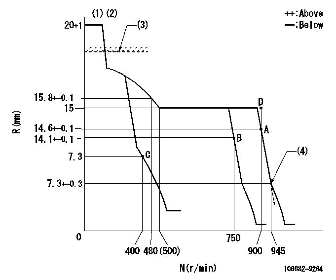
N:Pump speed
R:Rack position (mm)
(1)Target notch: K
(2)Tolerance for racks not indicated: +-0.05mm.
(3)RACK LIMIT for 106684-4203; RAL
(4)Idle sub spring setting: L1.
----------
K=24 RAL=15.5+0.2mm L1=7.3-0.2mm
----------
----------
K=24 RAL=15.5+0.2mm L1=7.3-0.2mm
----------
Speed control lever angle
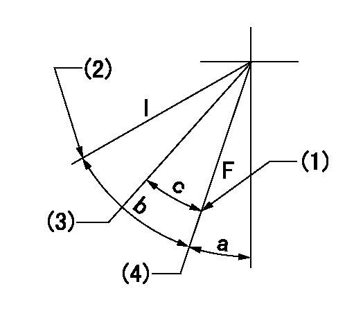
F:Full speed
I:Idle
(1)Stopper bolt setting
(2)Stopper bolt setting
(3)Set the pump speed at aa
(4)Set the pump speed at bb (at delivery)
----------
aa=750r/min bb=900r/min
----------
a=6deg+-5deg b=34deg+-5deg c=9deg+-5deg
----------
aa=750r/min bb=900r/min
----------
a=6deg+-5deg b=34deg+-5deg c=9deg+-5deg
Stop lever angle
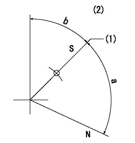
N:Pump normal
S:Stop the pump.
(1)Pump speed aa and rack position bb (to be sealed at delivery)
(2)No return spring
----------
aa=0r/min bb=1-0.5mm
----------
a=(73deg) b=43.5deg+-5deg
----------
aa=0r/min bb=1-0.5mm
----------
a=(73deg) b=43.5deg+-5deg
Timing setting

(1)Pump vertical direction
(2)Coupling's key groove position at No 1 cylinder's beginning of injection
(3)-
(4)-
----------
----------
a=(30deg)
----------
----------
a=(30deg)
Information:
Start By:a. remove timing gear cover 1. Remove bolt (1) and washer that fastens the weight assembly (2).
Weight assembly must have support during removal to prevent damage to components.
2. Install tooling (A) and remove the weight assembly.Install Automatic Timing Advance Unit
1. Install washer and bolt (1). With the fuel pump housing cover removed, turn the fuel pump camshaft in the direction of engine rotation until tool (A) can be installed in the notch of the camshaft. 2. To time the fuel injection pump to the engine with the front timing cover removed, follow Steps 3 and 4. With the timing cover installed, see Steps 6 and 7. No. 1 piston at top center (TC) on the compression stroke is the starting point for all timing procedures. The engine is seen from the flywheel end when direction of crankshaft rotation is given.3. Turn the crankshaft counterclockwise until the "C" on the crankshaft and camshaft and camshaft gears are in alignment. 4. Remove the plug and install tool (B) in the flywheel housing.5. To find top center compression stroke for No. 1 piston, turn the flywheel clockwise (opposite of engine rotation) approximately 30°. This procedure is to remove all end play from timing gears.6. Turn the flywheel counterclockwise (direction of engine rotation) until tool (B) can be installed in the flywheel. The piston is at top center. If you go past the bolt hole you must start over again. To see if the No. 1 piston is on the compression stroke, remove the breather assembly from the valve cover and look at the valves of the No. 1 cylinder. The valves will be closed if No. 1 cylinder is on the compression stroke. You must be able to move the rocker arms up and down with your hand.7. If NO. 1 piston is not on the compression stroke, remove tooling (B) and turn the flywheel 360° counterclockwise. Install tooling (B). The No. 1 piston is now at top center on the compression stroke.8. With tooling (A) and (B) installed in position, install the timing advance weight assembly on the fuel pump camshaft. 9. Use tool (D) to hold the gear. Install tooling (C) on the weight assembly. While a constant torque on drive gear on 68 N m (50 lb ft) is held, tighten the bolt that fastens the weight assembly to fuel pump camshaft to a torque of 270 25 N m (200 18 lb ft).10. Remove tooling (A), (B) and (C).End By:a. install timing gear coverDisassemble And Assemble Automatic Timing Unit
Start By:a. remove automatic timing advance unit
Keep all parts clean from contaminants. Contaminants put into the system may cause rapid wear and shortened component life.
1. Remove two screws (1) and plate (2).
The weights are held on position with two springs for each weight under compression. Carefully remove weights and springs to prevent possible injury.
2. Remove springs (4) and (5), weight (3) and slide (6) from each side of assembly. 3. If necessary, remove gear (7). Remove