Information injection-pump assembly
ZEXEL
106682-9261
1066829261
Rating:
Cross reference number
ZEXEL
106682-9261
1066829261
Zexel num
Bosch num
Firm num
Name
106682-9261
INJECTION-PUMP ASSEMBLY
Calibration Data:
Adjustment conditions
Test oil
1404 Test oil ISO4113 or {SAEJ967d}
1404 Test oil ISO4113 or {SAEJ967d}
Test oil temperature
degC
40
40
45
Nozzle and nozzle holder
105780-8130
Bosch type code
EFEP215A
Nozzle
105780-0050
Bosch type code
DN6TD119NP1T
Nozzle holder
105780-2090
Bosch type code
EFEP215
Opening pressure
MPa
17.2
Opening pressure
kgf/cm2
175
Injection pipe
Outer diameter - inner diameter - length (mm) mm 8-3-600
Outer diameter - inner diameter - length (mm) mm 8-3-600
Overflow valve
131425-1620
Overflow valve opening pressure
kPa
255
221
289
Overflow valve opening pressure
kgf/cm2
2.6
2.25
2.95
Tester oil delivery pressure
kPa
157
157
157
Tester oil delivery pressure
kgf/cm2
1.6
1.6
1.6
Direction of rotation (viewed from drive side)
Right R
Right R
Injection timing adjustment
Direction of rotation (viewed from drive side)
Right R
Right R
Injection order
1-5-3-6-
2-4
Pre-stroke
mm
2.8
2.75
2.85
Beginning of injection position
Drive side NO.1
Drive side NO.1
Difference between angles 1
Cal 1-5 deg. 60 59.5 60.5
Cal 1-5 deg. 60 59.5 60.5
Difference between angles 2
Cal 1-3 deg. 120 119.5 120.5
Cal 1-3 deg. 120 119.5 120.5
Difference between angles 3
Cal 1-6 deg. 180 179.5 180.5
Cal 1-6 deg. 180 179.5 180.5
Difference between angles 4
Cyl.1-2 deg. 240 239.5 240.5
Cyl.1-2 deg. 240 239.5 240.5
Difference between angles 5
Cal 1-4 deg. 300 299.5 300.5
Cal 1-4 deg. 300 299.5 300.5
Injection quantity adjustment
Adjusting point
A
Rack position
14.6
Pump speed
r/min
900
900
900
Average injection quantity
mm3/st.
520
515
525
Max. variation between cylinders
%
0
-3
3
Basic
*
Fixing the rack
*
Remarks
Standard point A's rack position same as 106684-4201 in row R.
Standard point A's rack position same as 106684-4201 in row R.
Injection quantity adjustment_02
Adjusting point
C
Rack position
7.3+-0.5
Pump speed
r/min
400
400
400
Average injection quantity
mm3/st.
21.5
20
23
Max. variation between cylinders
%
0
-15
15
Fixing the rack
*
Test data Ex:
Governor adjustment
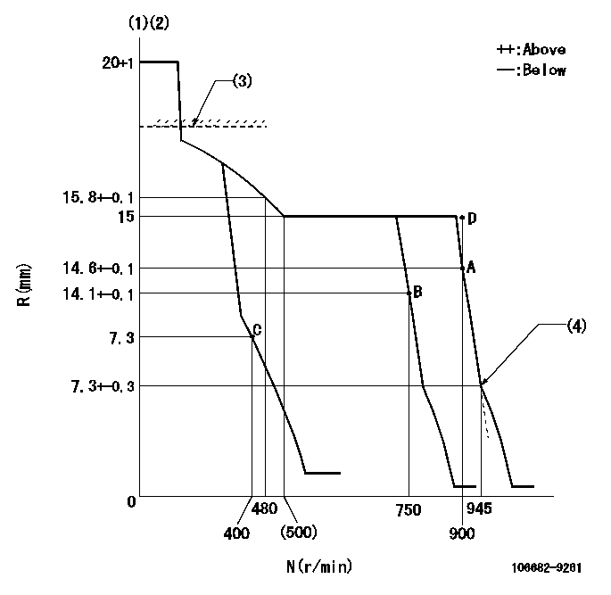
N:Pump speed
R:Rack position (mm)
(1)Target notch: K
(2)Tolerance for racks not indicated: +-0.05mm.
(3)RACK LIMIT for 106684-4201; RAL
(4)Idle sub spring setting: L1.
----------
K=24 RAL=15.5+0.2mm L1=7.3-0.2mm
----------
----------
K=24 RAL=15.5+0.2mm L1=7.3-0.2mm
----------
Speed control lever angle
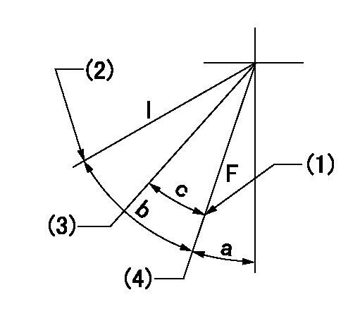
F:Full speed
I:Idle
(1)Stopper bolt setting
(2)Stopper bolt setting
(3)Set the pump speed at aa
(4)Set the pump speed at bb (at delivery)
----------
aa=750r/min bb=900r/min
----------
a=6deg+-5deg b=34deg+-5deg c=9deg+-5deg
----------
aa=750r/min bb=900r/min
----------
a=6deg+-5deg b=34deg+-5deg c=9deg+-5deg
Stop lever angle
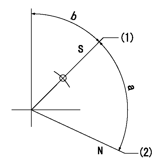
N:Pump normal
S:Stop the pump.
(1)Pump speed aa and rack position bb (to be sealed at delivery)
(2)Normal
----------
aa=0r/min bb=1-0.5mm
----------
a=(73deg) b=43.5deg+-5deg
----------
aa=0r/min bb=1-0.5mm
----------
a=(73deg) b=43.5deg+-5deg
Timing setting

(1)Pump vertical direction
(2)Coupling's key groove position at No 1 cylinder's beginning of injection
(3)-
(4)-
----------
----------
a=(30deg)
----------
----------
a=(30deg)
Information:
Start By:a. remove radiator
Keep all parts clean from contaminants. Contaminants put into the system may cause rapid wear and shortened component life.
1. Loosen bolt (4), bolt (5), and bolt (6). Remove belts (3).2. Remove bolts (2) and fan (1). 3. Remove bolt (7) and washer (8). Put enough spacers (10) on bolt (7) to get approximately 3.18 mm (.125 in) of clearance between washer (8) and vibration damper and pulley assembly (9). Install bolt (7), washer (8), and spacers (10).
If spacers (10) are not used, damage to the bolt and/or crankshaft can result when the vibration damper and pulley are removed from the crankshaft.
4. Install tool (A) as shown, and loosen vibration damper and pulley assembly (9).5. Remove tool (A), bolt (7), washer (8), spacers (10), and vibration damper and pulley assembly (9). 6. If necessary, remove bolts (11) and vibration damper (12). The following steps are to install the crankshaft vibration damper and pulley. Inspect the vibration damper housing for leakage or dents (damage housing). If either condition exists, a replacement of the vibration damper must be made.7. Install vibration damper (12) on pulley (13). Install bolts (11).8. Install vibration damper and pulley assembly (9) and install bolt (7), spacers (10) and washer (8).
The flat side of washer (8) must be installed toward vibration damper and pulley assembly (9).
9. Tighten bolt (7) to a torque of 284 to 340 N m (210 to 250 lb ft). Hit bolt (7) with a hammer and retighten to a torque of 284 to 340 N m (210 to 250 lb ft).10. Position belts (3). Tighten bolts (4), (5), and (6). Use a belt tension gauge and make an adjustment of the belts. Measure the belt farthest from the engine. Tighten new belts until the gauge indication is 534 22 N (120 5 lb ft). Operate the engine at high idle for a minimum of 30 minutes after installing radiator and guards. Make another adjustment of the belt tension. The correct gauge indication for a used belt is 400 44 N (90 10 lb.). Tighten bolt (4), bolt (5), and bolt (6).11. Install fan (1) and bolt (2).End By:a. install radiator
Have questions with 106682-9261?
Group cross 106682-9261 ZEXEL
106682-9261
INJECTION-PUMP ASSEMBLY