Information injection-pump assembly
ZEXEL
106682-9260
1066829260
Rating:
Cross reference number
ZEXEL
106682-9260
1066829260
Zexel num
Bosch num
Firm num
Name
106682-9260
INJECTION-PUMP ASSEMBLY
Calibration Data:
Adjustment conditions
Test oil
1404 Test oil ISO4113 or {SAEJ967d}
1404 Test oil ISO4113 or {SAEJ967d}
Test oil temperature
degC
40
40
45
Nozzle and nozzle holder
105780-8130
Bosch type code
EFEP215A
Nozzle
105780-0050
Bosch type code
DN6TD119NP1T
Nozzle holder
105780-2090
Bosch type code
EFEP215
Opening pressure
MPa
17.2
Opening pressure
kgf/cm2
175
Injection pipe
Outer diameter - inner diameter - length (mm) mm 8-4-1000
Outer diameter - inner diameter - length (mm) mm 8-4-1000
Overflow valve
131424-7120
Overflow valve opening pressure
kPa
255
221
289
Overflow valve opening pressure
kgf/cm2
2.6
2.25
2.95
Tester oil delivery pressure
kPa
157
157
157
Tester oil delivery pressure
kgf/cm2
1.6
1.6
1.6
Direction of rotation (viewed from drive side)
Right R
Right R
Injection timing adjustment
Direction of rotation (viewed from drive side)
Right R
Right R
Injection order
1-5-3-6-
2-4
Pre-stroke
mm
2.8
2.75
2.85
Beginning of injection position
Drive side NO.1
Drive side NO.1
Difference between angles 1
Cal 1-5 deg. 60 59.5 60.5
Cal 1-5 deg. 60 59.5 60.5
Difference between angles 2
Cal 1-3 deg. 120 119.5 120.5
Cal 1-3 deg. 120 119.5 120.5
Difference between angles 3
Cal 1-6 deg. 180 179.5 180.5
Cal 1-6 deg. 180 179.5 180.5
Difference between angles 4
Cyl.1-2 deg. 240 239.5 240.5
Cyl.1-2 deg. 240 239.5 240.5
Difference between angles 5
Cal 1-4 deg. 300 299.5 300.5
Cal 1-4 deg. 300 299.5 300.5
Injection quantity adjustment
Adjusting point
A
Rack position
14.4
Pump speed
r/min
900
900
900
Average injection quantity
mm3/st.
479
474
484
Max. variation between cylinders
%
0
-3
3
Basic
*
Fixing the rack
*
Remarks
Standard point A's rack position same as row R
Standard point A's rack position same as row R
Injection quantity adjustment_02
Adjusting point
C
Rack position
7.3+-0.5
Pump speed
r/min
400
400
400
Average injection quantity
mm3/st.
13
11.5
14.5
Max. variation between cylinders
%
0
-15
15
Fixing the rack
*
Test data Ex:
Governor adjustment
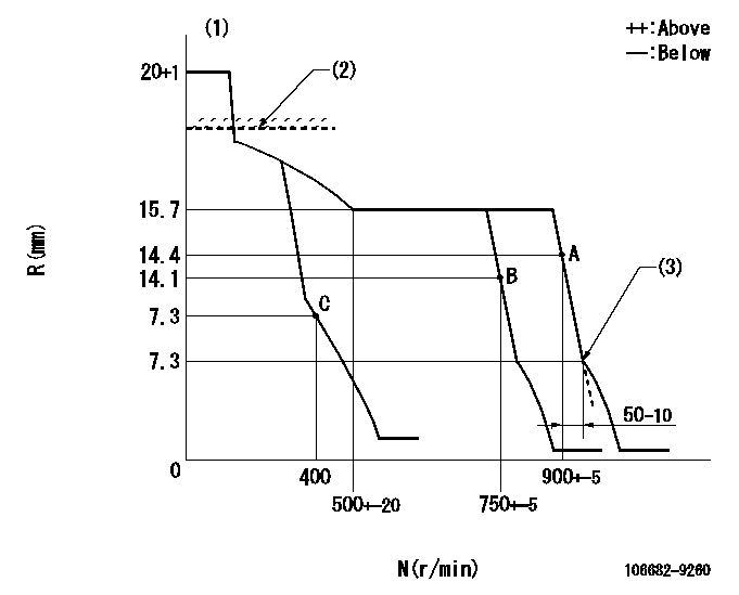
N:Pump speed
R:Rack position (mm)
(1)Target notch: K
(2)RACK LIMIT for 106684-4200
(3)Idle sub spring setting: L1.
----------
K=23 L1=7.3-0.2mm
----------
----------
K=23 L1=7.3-0.2mm
----------
Speed control lever angle
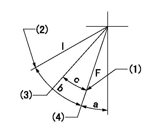
F:Full speed
I:Idle
(1)Stopper bolt setting
(2)Stopper bolt setting
(3)Set the pump speed at aa
(4)Set the pump speed at bb (at delivery)
----------
aa=750r/min bb=900r/min
----------
a=7.5deg+-5deg b=23.5deg+-5deg c=6.5deg+-5deg
----------
aa=750r/min bb=900r/min
----------
a=7.5deg+-5deg b=23.5deg+-5deg c=6.5deg+-5deg
Stop lever angle
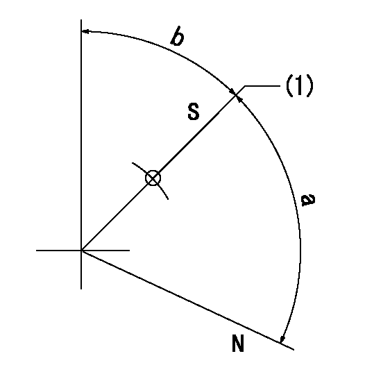
N:Pump normal
S:Stop the pump.
(1)Rack position = aa or less
----------
aa=2mm
----------
a=(73deg) b=43.5deg+-5deg
----------
aa=2mm
----------
a=(73deg) b=43.5deg+-5deg
Timing setting

(1)Pump vertical direction
(2)Coupling's key groove position at No 1 cylinder's beginning of injection
(3)-
(4)-
----------
----------
a=(30deg)
----------
----------
a=(30deg)
Information:
Start By:a. remove oil pumpb. remove oil pan plate
Keep all parts clean from contaminants. Contaminants put into the system may cause rapid wear and shortened component life.
1. Turn the crankshaft until two pistons are at the bottom center. Remove connecting rod caps (1) from the two connecting rods. Remove the lower half of the rod bearing from the rod bearing cap.
The connecting rod bolts are loose on the connecting rods and can fall out when the nuts are removed.
2. Push the connecting rods away from the crankshaft. Remove the upper half of the rod bearing from the connecting rod. Install the connecting rod bearings dry when the clearance checks are made. Put clean engine oil on the connecting rod bearings for final assembly.3. Install the upper half of the rod bearing in the connecting rod.4. Install the lower half of the rod bearing in the connecting rod cap. Be sure the tabs in the back of the connecting rod bearings are in the tab grooves of the connecting rod and cap. 5. Use Plastigage (A) to check the connecting rod bearing clearance.6. Put Plastigage (A) on the connecting rod bearing.7. Put 2P2506 Thread Lubricant on the threads of the rod bolts and seat surfaces of the nuts.
When connecting rod caps are installed, make sure the number on the side of the cap is next to and respective with the number on the side of the connecting rod.
Do not turn the crankshaft when Plastigage (A) is in position.
Do not use an impact wrench to tighten the nuts the additional 90°.
8. Install connecting rod cap (1). Install the nuts. Tighten the nuts to a torque of 40 4 N m (30 3 lb ft). Put a mark on each nut and the end of each bolt. Tighten the nuts 90° more. Remove the connecting rod caps. Remove Plastigage (A) and measure the width of the Plastigage. The connecting rod clearance must be 0.076 to 0.168 mm (.0030 to .0066 in) for new bearings. The maximum clearance with used bearings is 0.25 mm (.010 in).9. Install the connecting rod caps and tighten the nuts as in Step 8.10. Do Steps 1 through 9 for the remainder of the connecting rod bearings.End By:a. install oil pan plateb. install oil pump
Have questions with 106682-9260?
Group cross 106682-9260 ZEXEL
106682-9260
INJECTION-PUMP ASSEMBLY