Information injection-pump assembly
BOSCH
9 400 610 974
9400610974
ZEXEL
106682-9250
1066829250
KOMATSU
6212711560
6212711560
Rating:
Service parts 106682-9250 INJECTION-PUMP ASSEMBLY:
1.
_
5.
AUTOM. ADVANCE MECHANIS
7.
COUPLING PLATE
8.
_
9.
_
11.
Nozzle and Holder
6212-11-3202
12.
Open Pre:MPa(Kqf/cm2)
24.5{250}
15.
NOZZLE SET
Include in #1:
106682-9250
as INJECTION-PUMP ASSEMBLY
Cross reference number
BOSCH
9 400 610 974
9400610974
ZEXEL
106682-9250
1066829250
KOMATSU
6212711560
6212711560
Zexel num
Bosch num
Firm num
Name
Calibration Data:
Adjustment conditions
Test oil
1404 Test oil ISO4113 or {SAEJ967d}
1404 Test oil ISO4113 or {SAEJ967d}
Test oil temperature
degC
40
40
45
Nozzle and nozzle holder
105780-8130
Bosch type code
EFEP215A
Nozzle
105780-0050
Bosch type code
DN6TD119NP1T
Nozzle holder
105780-2090
Bosch type code
EFEP215
Opening pressure
MPa
17.2
Opening pressure
kgf/cm2
175
Injection pipe
Outer diameter - inner diameter - length (mm) mm 8-4-1000
Outer diameter - inner diameter - length (mm) mm 8-4-1000
Overflow valve
131424-3420
Overflow valve opening pressure
kPa
255
221
289
Overflow valve opening pressure
kgf/cm2
2.6
2.25
2.95
Tester oil delivery pressure
kPa
157
157
157
Tester oil delivery pressure
kgf/cm2
1.6
1.6
1.6
Direction of rotation (viewed from drive side)
Right R
Right R
Injection timing adjustment
Direction of rotation (viewed from drive side)
Right R
Right R
Injection order
1-5-3-6-
2-4
Pre-stroke
mm
2.8
2.75
2.85
Beginning of injection position
Drive side NO.1
Drive side NO.1
Difference between angles 1
Cal 1-5 deg. 60 59.5 60.5
Cal 1-5 deg. 60 59.5 60.5
Difference between angles 2
Cal 1-3 deg. 120 119.5 120.5
Cal 1-3 deg. 120 119.5 120.5
Difference between angles 3
Cal 1-6 deg. 180 179.5 180.5
Cal 1-6 deg. 180 179.5 180.5
Difference between angles 4
Cyl.1-2 deg. 240 239.5 240.5
Cyl.1-2 deg. 240 239.5 240.5
Difference between angles 5
Cal 1-4 deg. 300 299.5 300.5
Cal 1-4 deg. 300 299.5 300.5
Injection quantity adjustment
Adjusting point
A
Rack position
13.8
Pump speed
r/min
900
900
900
Average injection quantity
mm3/st.
423
418
428
Max. variation between cylinders
%
0
-3
3
Basic
*
Fixing the rack
*
Injection quantity adjustment_02
Adjusting point
C
Rack position
7.3+-0.5
Pump speed
r/min
410
410
410
Average injection quantity
mm3/st.
17
15.5
18.5
Max. variation between cylinders
%
0
-15
15
Fixing the rack
*
Injection quantity adjustment_03
Adjusting point
D
Rack position
-
Pump speed
r/min
100
100
100
Average injection quantity
mm3/st.
400
390
410
Fixing the lever
*
Rack limit
*
Test data Ex:
Governor adjustment
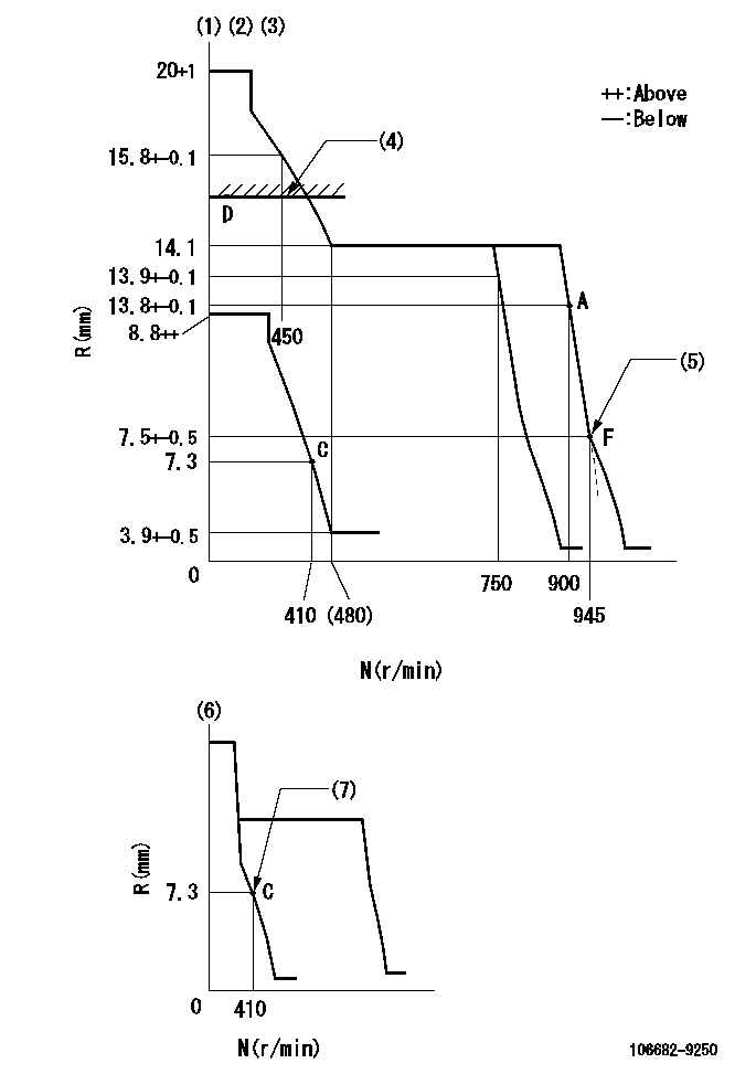
N:Pump speed
R:Rack position (mm)
(1)Minimum - maximum speed specification
(2)Target notch: K
(3)Tolerance for racks not indicated: +-0.05mm.
(4)RACK LIMIT
(5)Idle sub-spring setting: L1
(6)Variable speed specification: idling adjustment
(7)Main spring setting
----------
K=14 L1=7.5-0.5mm
----------
----------
K=14 L1=7.5-0.5mm
----------
Speed control lever angle
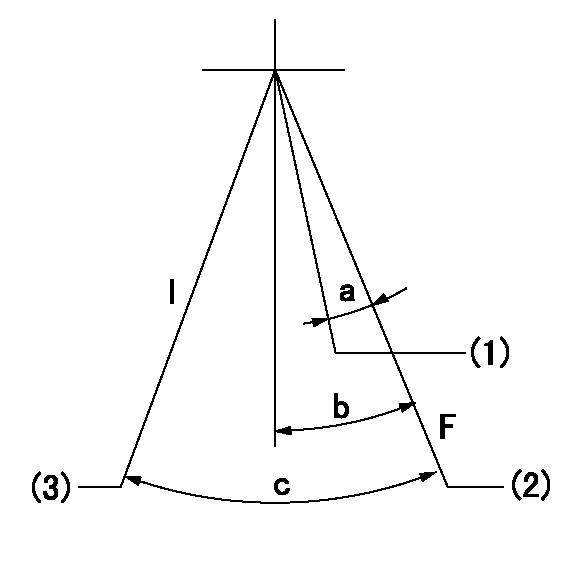
F:Full speed
I:Idle
(1)Set the pump speed at aa
(2)Set the pump speed at bb (at delivery)
(3)Stopper bolt setting
----------
aa=750r/min bb=900r/min
----------
a=9deg+-5deg b=17deg+-5deg c=31deg+-5deg
----------
aa=750r/min bb=900r/min
----------
a=9deg+-5deg b=17deg+-5deg c=31deg+-5deg
0000000901
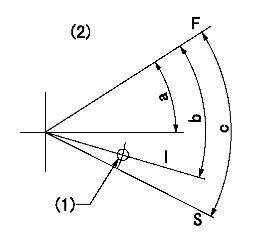
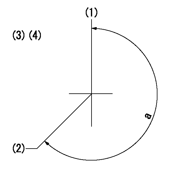
F:Full load
I:Idle
S:Stop
(1)Use the hole at R = aa
(2)Without return spring
----------
aa=27mm
----------
a=26.5deg+-5deg b=27deg+-5deg c=53deg+-5deg
----------
aa=27mm
----------
a=26.5deg+-5deg b=27deg+-5deg c=53deg+-5deg
Timing setting
(1)Pump vertical direction
(2)Coupling's key groove position at No 1 cylinder's beginning of injection
(3)-
(4)-
----------
----------
a=(260deg)
----------
----------
a=(260deg)
Information:
Start By:a. remove spacer plate
Keep all parts clean from contaminants. Contaminants put into the system may cause rapid wear and shortened component life.
1. Put compression on valve spring (2) with tool (A), and remove locks (1).2. Remove tool (A), rotocoil, spring, valve stem oil shield and valve. Put identification marks on valves with respect to their location in the cylinder head. 3. Check the spring force with tool (B). The spring force is 257 25 N (57.8 5.6 lb.). The length of spring under test force is 44.86 mm (1.766 in). The free length after test is 52.07 mm (2.050 in).4. Perform Steps 1 through 3 again for the remainder of the valves. The following steps are for the installation of the valves.5. Put clean engine oil on the valve stems. Install the valve, oil shield, spring (2) and rotocoil in the cylinder head. 6. Put tool (A) in position on the valve spring, and install the locks with tool (C).
Locks can be thrown from valve when the compressor is released if they are not in their correct position on valve stem. Personal injury can be the result if not carefully removed.
7. Remove tool (A), and hit the top of valve with a plastic hammer be sure the locks are in their correct position on valve.8. Do Steps 5 through 7 again for the remainder of the valves.End By:a. install spacer plate