Information injection-pump assembly
ZEXEL
106682-9240
1066829240
KOMATSU
6152751260
6152751260
Rating:
Service parts 106682-9240 INJECTION-PUMP ASSEMBLY:
1.
_
5.
AUTOM. ADVANCE MECHANIS
6.
COUPLING PLATE
8.
_
9.
_
10.
NOZZLE AND HOLDER ASSY
11.
Nozzle and Holder
12.
Open Pre:MPa(Kqf/cm2)
26.0{265}
13.
NOZZLE-HOLDER
14.
NOZZLE
15.
NOZZLE SET
Include in #1:
106682-9240
as INJECTION-PUMP ASSEMBLY
Cross reference number
ZEXEL
106682-9240
1066829240
KOMATSU
6152751260
6152751260
Zexel num
Bosch num
Firm num
Name
Calibration Data:
Adjustment conditions
Test oil
1404 Test oil ISO4113 or {SAEJ967d}
1404 Test oil ISO4113 or {SAEJ967d}
Test oil temperature
degC
40
40
45
Nozzle and nozzle holder
105780-8130
Bosch type code
EFEP215A
Nozzle
105780-0050
Bosch type code
DN6TD119NP1T
Nozzle holder
105780-2090
Bosch type code
EFEP215
Opening pressure
MPa
17.2
Opening pressure
kgf/cm2
175
Injection pipe
Outer diameter - inner diameter - length (mm) mm 8-4-1000
Outer diameter - inner diameter - length (mm) mm 8-4-1000
Overflow valve
131424-7120
Overflow valve opening pressure
kPa
255
221
289
Overflow valve opening pressure
kgf/cm2
2.6
2.25
2.95
Tester oil delivery pressure
kPa
157
157
157
Tester oil delivery pressure
kgf/cm2
1.6
1.6
1.6
Direction of rotation (viewed from drive side)
Left L
Left L
Injection timing adjustment
Direction of rotation (viewed from drive side)
Left L
Left L
Injection order
1-5-3-6-
2-4
Pre-stroke
mm
2.8
2.75
2.85
Beginning of injection position
Drive side NO.1
Drive side NO.1
Difference between angles 1
Cal 1-5 deg. 60 59.5 60.5
Cal 1-5 deg. 60 59.5 60.5
Difference between angles 2
Cal 1-3 deg. 120 119.5 120.5
Cal 1-3 deg. 120 119.5 120.5
Difference between angles 3
Cal 1-6 deg. 180 179.5 180.5
Cal 1-6 deg. 180 179.5 180.5
Difference between angles 4
Cyl.1-2 deg. 240 239.5 240.5
Cyl.1-2 deg. 240 239.5 240.5
Difference between angles 5
Cal 1-4 deg. 300 299.5 300.5
Cal 1-4 deg. 300 299.5 300.5
Injection quantity adjustment
Adjusting point
A
Rack position
14.7
Pump speed
r/min
1100
1100
1100
Average injection quantity
mm3/st.
371
368
374
Max. variation between cylinders
%
0
-3
3
Basic
*
Fixing the lever
*
Boost pressure
kPa
49.3
49.3
Boost pressure
mmHg
370
370
Injection quantity adjustment_02
Adjusting point
C
Rack position
7.7+-0.5
Pump speed
r/min
275
275
275
Average injection quantity
mm3/st.
8.5
6.5
10.5
Max. variation between cylinders
%
0
-15
15
Fixing the rack
*
Boost pressure
kPa
0
0
0
Boost pressure
mmHg
0
0
0
Injection quantity adjustment_03
Adjusting point
D
Rack position
-
Pump speed
r/min
100
100
100
Average injection quantity
mm3/st.
320
320
340
Fixing the lever
*
Boost pressure
kPa
0
0
0
Boost pressure
mmHg
0
0
0
Rack limit
*
Boost compensator adjustment
Pump speed
r/min
600
600
600
Rack position
R1-3.1
Boost pressure
kPa
4
2.7
5.3
Boost pressure
mmHg
30
20
40
Boost compensator adjustment_02
Pump speed
r/min
600
600
600
Rack position
R1(14.7)
Boost pressure
kPa
36
29.3
42.7
Boost pressure
mmHg
270
220
320
Test data Ex:
Governor adjustment
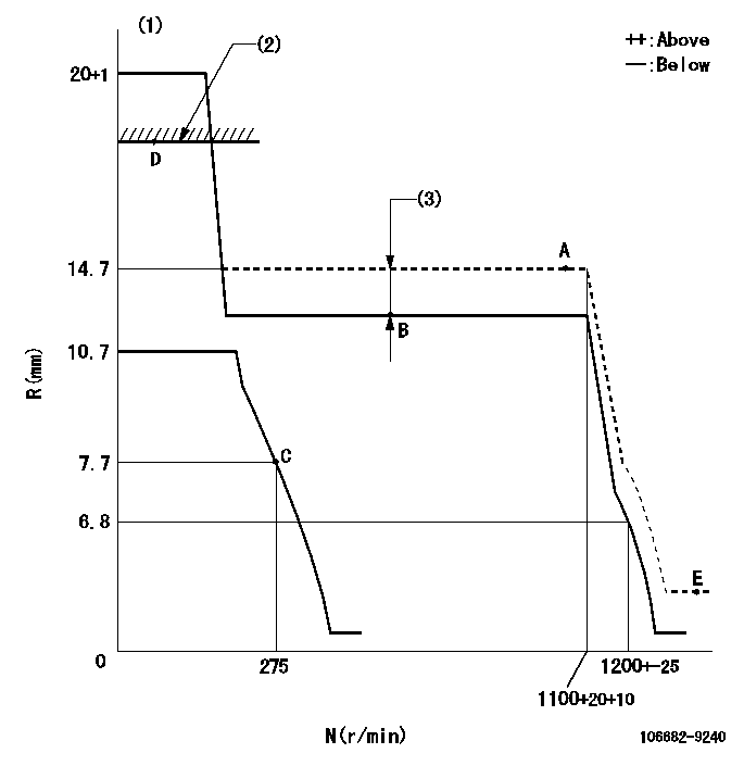
N:Pump speed
R:Rack position (mm)
(1)Target notch: K
(2)RACK LIMIT
(3)Boost compensator stroke: BCL
----------
K=24 BCL=3.1+-0.1mm
----------
----------
K=24 BCL=3.1+-0.1mm
----------
Speed control lever angle
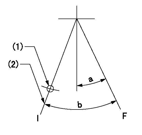
F:Full speed
I:Idle
(1)Use the hole at R = aa
(2)Stopper bolt setting
----------
aa=90mm
----------
a=15deg+-5deg b=35deg+-5deg
----------
aa=90mm
----------
a=15deg+-5deg b=35deg+-5deg
Stop lever angle
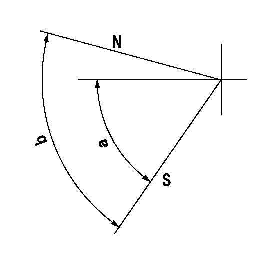
N:Pump normal
S:Stop the pump.
----------
----------
a=58deg+-5deg b=(73deg)
----------
----------
a=58deg+-5deg b=(73deg)
Timing setting

(1)Pump vertical direction
(2)Coupling's key groove position at No 1 cylinder's beginning of injection
(3)-
(4)-
----------
----------
a=(160deg)
----------
----------
a=(160deg)
Information:
Keep all parts clean from contaminants. Contaminants put into the system may cause rapid wear and shortened component life.
1. Drain the cooling system. 2. Loosen hose clamps (1) and (3). Disconnect hoses (2) and (4). 3. Support pump (5) and remove four bolts (6). 4. Remove elbow (7) and the gasket. The following steps are to install the water pump.5. Install a new gasket and elbow (7).6. Put the water pump (5) and elbow (7) in position and install four bolts (6).7. Put hoses (2) and (4) in position on elbow (7) and tighten the clamps (1) and (3).8. Fill the cooling system to the correct level. See the Maintenance Manual.Disassemble And Assemble Water Pump
Start By:a. remove water pump
Keep all parts clean from contaminants. Contaminants put into the system may cause rapid wear and shortened component life.
1. Remove bolt (15) and the washer. Remove bearing (12) and gear (10) as a unit.2. Use tooling (A), (C) and a press, and remove bearing (12) from gear (10).3. Remove snap ring (8) with tool (B).4. Remove two bolts (1), the washers, cover (14) and gasket (2) from water pump housing (18).5. Loosen bolt (13) approximately 6.4 mm (.25 in). Hit the bolt with a soft hammer to loosen impeller (16).6. Remove bolt (13), washer (11), impeller (16), spring (3) and seal assembly (4).7. Remove bearing (7) and shaft (9) as a unit.8. Use tooling (A), (C) and a press to remove bearing (7).9. Remove ceramic seal (5) and seal (17).10. Use tool (C) to remove lip-type seal (6). The following steps are for assembly of the water pump.11. Install hydrodynamic seal (6) in water pump housing (18) with tool (C). The lip of the seal must be toward the bearings. Put clean engine oil on the lip of the seal.12. Install shaft (9) in bearing (7) with a press.13. Install shaft (9) and bearing (7) as a unit in water pump housing (18).14. Install snap ring (8) with tool (B).
Clean water only is permitted for use as a lubricant for assembly. Do not damage or put hands on the wear surface of the carbon ring or the ceramic ring. Install the ceramic ring with the smoothest face of the ring toward the carbon seal assembly.
15. Put ceramic ring (5) in position in seal (17). Use hand pressure and tool (D) to install the ceramic ring.16. Remove spring (3) from seal assembly (4). Use hand pressure and tool (D) to install the seal assembly. Push seal assembly (4) on shaft (9) until it makes light contact with ceramic ring (5).17. Install spring (3) on seal assembly (4). Put impeller (16) in position on shaft (9), and install washer (11) and bolt (13). Tighten bolt (13) to a torque of 38.0 1.5 N m (28 1 lb ft).18. Put gasket (2) and cover (14) in position and install the two washers and bolts (1).19. Install bearing (12) on gear (10) with a press.20. Position gear (10) and bearing (12) as