Information injection-pump assembly
ZEXEL
106682-9230
1066829230
KOMATSU
6212711540
6212711540
Rating:
Cross reference number
ZEXEL
106682-9230
1066829230
KOMATSU
6212711540
6212711540
Zexel num
Bosch num
Firm num
Name
Calibration Data:
Adjustment conditions
Test oil
1404 Test oil ISO4113 or {SAEJ967d}
1404 Test oil ISO4113 or {SAEJ967d}
Test oil temperature
degC
40
40
45
Nozzle and nozzle holder
105780-8130
Bosch type code
EFEP215A
Nozzle
105780-0050
Bosch type code
DN6TD119NP1T
Nozzle holder
105780-2090
Bosch type code
EFEP215
Opening pressure
MPa
17.2
Opening pressure
kgf/cm2
175
Injection pipe
Outer diameter - inner diameter - length (mm) mm 8-4-1000
Outer diameter - inner diameter - length (mm) mm 8-4-1000
Overflow valve
131424-3420
Overflow valve opening pressure
kPa
255
221
289
Overflow valve opening pressure
kgf/cm2
2.6
2.25
2.95
Tester oil delivery pressure
kPa
157
157
157
Tester oil delivery pressure
kgf/cm2
1.6
1.6
1.6
RED3 control unit part number
407910-3
960
RED3 rack sensor specifications
mm
19
Direction of rotation (viewed from drive side)
Right R
Right R
Injection timing adjustment
Direction of rotation (viewed from drive side)
Right R
Right R
Injection order
1-5-3-6-
2-4
Pre-stroke
mm
3.1
3.05
3.15
Beginning of injection position
Drive side NO.1
Drive side NO.1
Difference between angles 1
Cal 1-5 deg. 60 59.5 60.5
Cal 1-5 deg. 60 59.5 60.5
Difference between angles 2
Cal 1-3 deg. 120 119.5 120.5
Cal 1-3 deg. 120 119.5 120.5
Difference between angles 3
Cal 1-6 deg. 180 179.5 180.5
Cal 1-6 deg. 180 179.5 180.5
Difference between angles 4
Cyl.1-2 deg. 240 239.5 240.5
Cyl.1-2 deg. 240 239.5 240.5
Difference between angles 5
Cal 1-4 deg. 300 299.5 300.5
Cal 1-4 deg. 300 299.5 300.5
Injection quantity adjustment
Rack position
(15.4)
Vist
V
1.55
1.55
1.55
Pump speed
r/min
900
900
900
Average injection quantity
mm3/st.
459
454
464
Max. variation between cylinders
%
0
-3
3
Basic
*
Injection quantity adjustment_02
Rack position
(6.2)
Vist
V
2.9
2.8
3
Pump speed
r/min
400
400
400
Average injection quantity
mm3/st.
17.5
16
19
Max. variation between cylinders
%
0
-15
15
Test data Ex:
Speed control lever angle

N:Pump normal
S:Stop the pump.
(1)Rack position = aa
(2)Rack position bb
----------
aa=20mm bb=1mm
----------
a=27deg+-5deg b=37deg+-5deg
----------
aa=20mm bb=1mm
----------
a=27deg+-5deg b=37deg+-5deg
0000000901
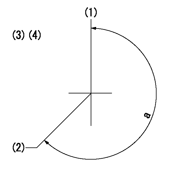
(1)Pump vertical direction
(2)Coupling's key groove position at No 1 cylinder's beginning of injection
(3)-
(4)-
----------
----------
a=(260deg)
----------
----------
a=(260deg)
Stop lever angle

(Rs) rack sensor specifications
(C/U) control unit part number
(V) Rack sensor output voltage
(R) Rack position (mm)
1. Confirming governor output characteristics (rack 19 mm, span 6 mm)
(1)When the output voltages of the rack sensor are V1 and V2, check that the rack positions R1 and R2 in the table above are satisfied.
----------
----------
----------
----------
Information:
1. Turn the fuel supply line valve to the "OFF" position.2. Remove tube assembly (2) and tube assembly (4).3. Remove bolts (1) and (5). Remove fuel transfer pump (3). Remove the O-ring seal from the fuel transfer pump if necessary. Assemble in reverse order.Disassemble And Assemble Fuel Transfer Pump
Start By:a. remove fuel transfer pump
Keep all parts clean from contaminants. Contaminants put into the system may cause rapid wear and shortened component life.
1. Remove bolts (2) and cover (1) from fuel transfer pump housing (11). Remove seals (5) and (6), and valve (4).2. Remove spring (3), washer (7), valve (13), seal (8), sleeve (9), and piston (10). Remove seal (19).3. Remove seal (14) and guide and tappet assembly (12).4. Remove screw (17), cover (18) and seal (16). Remove valve assembly (15).5. To assemble fuel transfer pump, install valve assembly (15) in the fuel transfer pump housing. Lubricate seal (16) lightly and install it with cover (18) and screw (17).
The tappet and guide of the guide and tappet assembly must be serviced as a unit.
6. Install seal (14) and guide and tappet assembly (12) in the fuel transfer pump housing.7. Install seal (19) on sleeve (9). Install piston (10), sleeve (9), seal (8), valve (13), and washer (7). Install spring (3).8. Install seal (5), seal (6), and valve (4). Install cover (1) and bolts (2).End By:a. install fuel transfer pump