Information injection-pump assembly
ZEXEL
106682-9220
1066829220
KOMATSU
6162732340
6162732340
Rating:
Service parts 106682-9220 INJECTION-PUMP ASSEMBLY:
1.
_
5.
AUTOM. ADVANCE MECHANIS
7.
COUPLING PLATE
8.
_
9.
_
11.
Nozzle and Holder
6166-11-3100
12.
Open Pre:MPa(Kqf/cm2)
26.0{265}
15.
NOZZLE SET
Include in #1:
106682-9220
as INJECTION-PUMP ASSEMBLY
Cross reference number
ZEXEL
106682-9220
1066829220
KOMATSU
6162732340
6162732340
Zexel num
Bosch num
Firm num
Name
Calibration Data:
Adjustment conditions
Test oil
1404 Test oil ISO4113 or {SAEJ967d}
1404 Test oil ISO4113 or {SAEJ967d}
Test oil temperature
degC
40
40
45
Nozzle and nozzle holder
105780-8130
Bosch type code
EFEP215A
Nozzle
105780-0050
Bosch type code
DN6TD119NP1T
Nozzle holder
105780-2090
Bosch type code
EFEP215
Opening pressure
MPa
17.2
Opening pressure
kgf/cm2
175
Injection pipe
Outer diameter - inner diameter - length (mm) mm 8-4-1000
Outer diameter - inner diameter - length (mm) mm 8-4-1000
Overflow valve
131425-1620
Overflow valve opening pressure
kPa
255
221
289
Overflow valve opening pressure
kgf/cm2
2.6
2.25
2.95
Tester oil delivery pressure
kPa
157
157
157
Tester oil delivery pressure
kgf/cm2
1.6
1.6
1.6
Direction of rotation (viewed from drive side)
Left L
Left L
Injection timing adjustment
Direction of rotation (viewed from drive side)
Left L
Left L
Injection order
1-5-3-6-
2-4
Pre-stroke
mm
2.8
2.75
2.85
Beginning of injection position
Drive side NO.1
Drive side NO.1
Difference between angles 1
Cal 1-5 deg. 60 59.5 60.5
Cal 1-5 deg. 60 59.5 60.5
Difference between angles 2
Cal 1-3 deg. 120 119.5 120.5
Cal 1-3 deg. 120 119.5 120.5
Difference between angles 3
Cal 1-6 deg. 180 179.5 180.5
Cal 1-6 deg. 180 179.5 180.5
Difference between angles 4
Cyl.1-2 deg. 240 239.5 240.5
Cyl.1-2 deg. 240 239.5 240.5
Difference between angles 5
Cal 1-4 deg. 300 299.5 300.5
Cal 1-4 deg. 300 299.5 300.5
Injection quantity adjustment
Adjusting point
A
Rack position
15.9
Pump speed
r/min
900
900
900
Average injection quantity
mm3/st.
606
601
611
Max. variation between cylinders
%
0
-3
3
Basic
*
Fixing the lever
*
Injection quantity adjustment_02
Adjusting point
B
Rack position
7.2+-0.5
Pump speed
r/min
400
400
400
Average injection quantity
mm3/st.
36
31
41
Max. variation between cylinders
%
0
-15
15
Fixing the rack
*
Injection quantity adjustment_03
Adjusting point
D
Rack position
16.5+-0.
5
Pump speed
r/min
100
100
100
Average injection quantity
mm3/st.
520
520
540
Fixing the lever
*
Rack limit
*
Test data Ex:
Governor adjustment
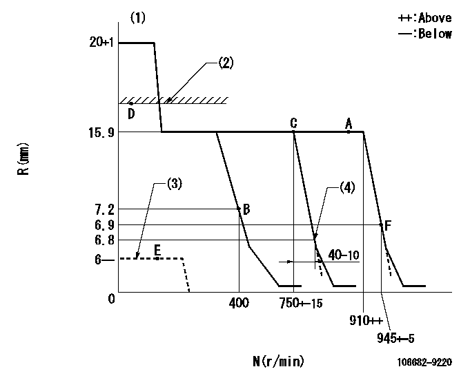
N:Pump speed
R:Rack position (mm)
(1)Notch fixed: K
(2)RACK LIMIT
(3)Stop lever at stopping (with the stop lever at full)
(4)Idle sub spring setting: L1.
----------
K=15 L1=6.8-0.5mm
----------
----------
K=15 L1=6.8-0.5mm
----------
Speed control lever angle
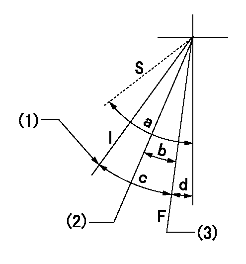
F:Full speed
I:Idle
S:Stop
(1)Stopper bolt setting
(2)Set the pump speed at aa
(3)Set speed at bb (setting at delivery), set stopper bolt.
----------
aa=750r/min bb=900r/min
----------
a=58deg+-3deg b=14deg+-5deg c=36deg+-5deg d=6deg+-5deg
----------
aa=750r/min bb=900r/min
----------
a=58deg+-3deg b=14deg+-5deg c=36deg+-5deg d=6deg+-5deg
Stop lever angle
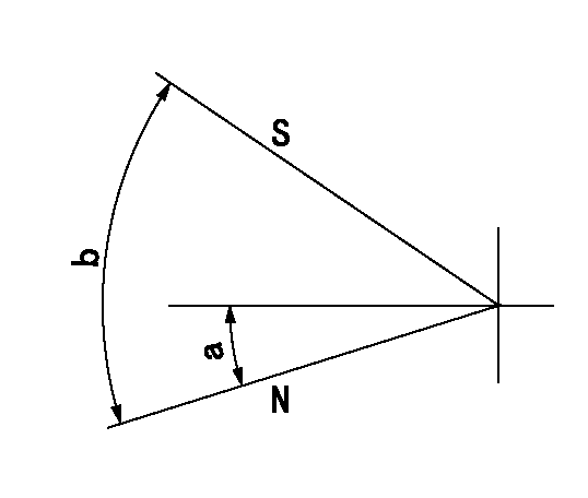
N:Pump normal
S:Stop the pump.
----------
----------
a=26.5deg+-5deg b=53deg+-5deg
----------
----------
a=26.5deg+-5deg b=53deg+-5deg
Timing setting

(1)Pump vertical direction
(2)Coupling's key groove position at No 1 cylinder's beginning of injection
(3)-
(4)-
----------
----------
a=(30deg)
----------
----------
a=(30deg)
Information:
Start By:a. remove governor **See Disassemble Governor story
Keep all parts clean from contaminants. Contaminants put into the system may cause rapid wear and shortened component life.
1. Remove the bolts and the plate from the side of the fuel injection pump housing. 2. Install tool (A) in the fuel injection pump housing. Move the rack until tool (A) can be installed to hold the rack in the center position to remove the fuel injection pumps.3. Use tool (B) to remove bushing (1).4. Remove the O-ring seal from the fuel injection pump housing. 5. Install tool (C) on the bonnet and remove the fuel injection pump. 6. Remove spacer (2). Keep the spacers (2) from the fuel injection pumps together with identification as to their location in the pump housing.7. Perform steps 3 through 6 to remove the other fuel injection pumps. The following steps are to install the fuel injection pumps.8. Install spacer (2).9. Install tool (A). Move the rack until tool (A) can be installed to hold the rack in the center position. The rack must be in the center position to install the fuel injection pumps.10. Turn camshaft until the lobe of the camshaft is down for the pump to be installed.11. Install tool (C) on the bonnet on the fuel injection pump.12. Install the fuel injection pump in the pump housing with saw cut slot in the gear in alignment with the small pin and groove in the barrel in alignment with dowel in the pump housing.13. Put clean oil on O-ring seal and install it in the fuel injection pump housing.14. Install the bushing by hand until the bushing is even with the top of the housing. If the bushing can not be installed this far by hand, remove it. Remove the fuel injection pump ad put the pump in alignment again and install the bushing again.15. Install tool (B) on the bushing and tighten the bushing to a torque of 190 14 N m (140 10 lb ft).16. Install tooling (D) to measure total rack travel. Correct rack travel is 15.7 mm (.618 in). A smaller measurement is an indication of improper fuel injection pump installation.17. Perform Steps 1 through 9 to install the other fuel pumps18. Install the cover and gasket on the fuel injection pump housing.End By:a. install governor **See Assemble Governor storyDisassemble And Assemble Fuel Injection Pumps
Start By:a. remove fuel injection pumps
When the injection pumps are disassembled, handle the parts carefully. Do not damage the surfaces of the plungers, barrels and bonnets. Any scratches will cause leakage inside the fuel injection pump. The plunger and barrel for each pump are made as a set. Do not intermix the plunger of one pump in the barrel with another pump. If one part is worn, install a complete new pump assembly. Be careful when placing the plunger into the bore of the barrel.
1. Pull plunger (1) and washer (5) out of barrel (3) and spring (2).
Do not remove the gear from