Information injection-pump assembly
ZEXEL
106682-9210
1066829210
Rating:
Cross reference number
ZEXEL
106682-9210
1066829210
Zexel num
Bosch num
Firm num
Name
106682-9210
INJECTION-PUMP ASSEMBLY
Calibration Data:
Adjustment conditions
Test oil
1404 Test oil ISO4113 or {SAEJ967d}
1404 Test oil ISO4113 or {SAEJ967d}
Test oil temperature
degC
40
40
45
Nozzle and nozzle holder
105780-8130
Bosch type code
EFEP215A
Nozzle
105780-0050
Bosch type code
DN6TD119NP1T
Nozzle holder
105780-2090
Bosch type code
EFEP215
Opening pressure
MPa
17.2
Opening pressure
kgf/cm2
175
Injection pipe
Outer diameter - inner diameter - length (mm) mm 8-4-1000
Outer diameter - inner diameter - length (mm) mm 8-4-1000
Overflow valve
131425-1620
Overflow valve opening pressure
kPa
255
221
289
Overflow valve opening pressure
kgf/cm2
2.6
2.25
2.95
Tester oil delivery pressure
kPa
157
157
157
Tester oil delivery pressure
kgf/cm2
1.6
1.6
1.6
Direction of rotation (viewed from drive side)
Right R
Right R
Injection timing adjustment
Direction of rotation (viewed from drive side)
Right R
Right R
Injection order
1-5-3-6-
2-4
Pre-stroke
mm
3.5
3.45
3.55
Beginning of injection position
Drive side NO.1
Drive side NO.1
Difference between angles 1
Cal 1-5 deg. 60 59.5 60.5
Cal 1-5 deg. 60 59.5 60.5
Difference between angles 2
Cal 1-3 deg. 120 119.5 120.5
Cal 1-3 deg. 120 119.5 120.5
Difference between angles 3
Cal 1-6 deg. 180 179.5 180.5
Cal 1-6 deg. 180 179.5 180.5
Difference between angles 4
Cyl.1-2 deg. 240 239.5 240.5
Cyl.1-2 deg. 240 239.5 240.5
Difference between angles 5
Cal 1-4 deg. 300 299.5 300.5
Cal 1-4 deg. 300 299.5 300.5
Injection quantity adjustment
Adjusting point
A
Rack position
14.1
Pump speed
r/min
900
900
900
Average injection quantity
mm3/st.
331
328
334
Max. variation between cylinders
%
0
-3
3
Basic
*
Fixing the lever
*
Remarks
Standard point A's rack position same as row R
Standard point A's rack position same as row R
Injection quantity adjustment_02
Adjusting point
B
Rack position
7.7+-0.5
Pump speed
r/min
400
400
400
Average injection quantity
mm3/st.
19
17.5
20.5
Max. variation between cylinders
%
0
-15
15
Fixing the rack
*
Test data Ex:
Governor adjustment
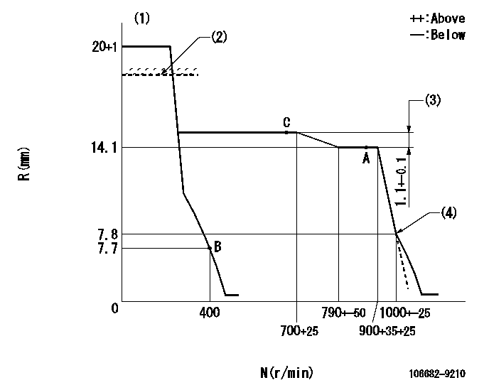
N:Pump speed
R:Rack position (mm)
(1)Target notch: K
(2)RACK LIMIT for 106684-4190; RAL
(3)Rack difference between N = N1 and N = N2
(4)Idle sub spring setting: L1.
----------
K=14 RAL=15.7+0.2mm N1=900r/min N2=700r/min L1=7.8-0.5mm
----------
----------
K=14 RAL=15.7+0.2mm N1=900r/min N2=700r/min L1=7.8-0.5mm
----------
Speed control lever angle
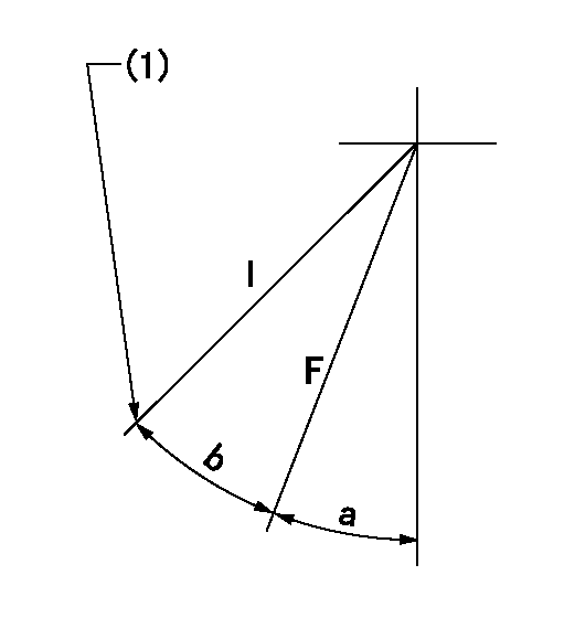
F:Full speed
I:Idle
(1)Stopper bolt setting
----------
----------
a=(21deg)+-5deg b=(21deg)+-5deg
----------
----------
a=(21deg)+-5deg b=(21deg)+-5deg
Stop lever angle
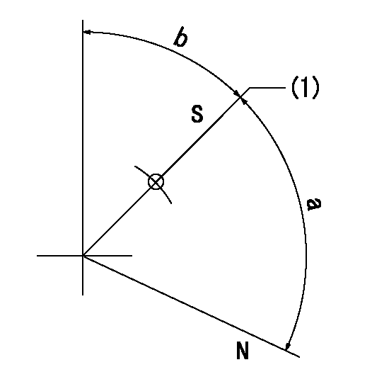
N:Pump normal
S:Stop the pump.
(1)Pump speed aa, rack position bb
----------
aa=0r/min bb=1-0.5mm
----------
a=(73deg) b=43.5deg+-5deg
----------
aa=0r/min bb=1-0.5mm
----------
a=(73deg) b=43.5deg+-5deg
Timing setting

(1)Pump vertical direction
(2)Coupling's key groove position at No 1 cylinder's beginning of injection
(3)-
(4)-
----------
----------
a=(30deg)
----------
----------
a=(30deg)
Information:
Keep all parts clean from contaminants. Contaminants put into the system may cause rapid wear and shortened component life.
1. Remove the bolts holding gasket assemblies (1) and (2) to the cylinder head. 2. Disconnect six fuel injection line nuts (3).
Do not allow the tops of nozzles (4) to turn while the fuel lines are loosened. The nozzles will be damaged if the top of the nozzle turns in the body. Defective fuel nozzles will damage the engine due to incorrect spray patterns.
3. Hold the tops on the fuel nozzles (4) with a wrench and loosen the fuel line nuts at the nozzles.4. Disconnect the fuel injection line nuts at the nozzles and remove the fuel injection lines.5. Install caps and plugs on the nozzles, fuel lines and in the fuel injection pump to keep dirt from contaminating the fuel system. The following steps are for installation.
Do not let the tops of nozzles (4) turn while the fuel lines are tightened. The nozzles will be damaged if the top of the nozzle turns in the body. Defective fuel nozzles will damage the engine due to improper spray patterns.
6. Remove protection covers from the fuel line connections. Place the fuel injection lines in position and install the fuel injection line nuts finger tight. 7. While holding the tops of fuel nozzles (4), use tool (A) and tighten the fuel injection line nuts to a torque of 40 7 N m (30 5 lb ft).8. Tighten the six fuel injection line nuts (3) at the fuel injection pumps to a torque of 40 7 N m (30 5 lb ft).9. Install the bolts that hold brackets (1) and (2) to the cylinder head. Remove the air from the fuel lines*. See the topic, Priming The Fuel System, in the Maintenance Manual.
Have questions with 106682-9210?
Group cross 106682-9210 ZEXEL
Komatsu
106682-9210
INJECTION-PUMP ASSEMBLY