Information injection-pump assembly
ZEXEL
106682-9200
1066829200
KOMATSU
6212711530
6212711530
Rating:
Service parts 106682-9200 INJECTION-PUMP ASSEMBLY:
1.
_
5.
AUTOM. ADVANCE MECHANIS
7.
COUPLING PLATE
8.
_
9.
_
11.
Nozzle and Holder
6212-11-3202
12.
Open Pre:MPa(Kqf/cm2)
24.5{250}
15.
NOZZLE SET
Include in #1:
106682-9200
as INJECTION-PUMP ASSEMBLY
Cross reference number
ZEXEL
106682-9200
1066829200
KOMATSU
6212711530
6212711530
Zexel num
Bosch num
Firm num
Name
Calibration Data:
Adjustment conditions
Test oil
1404 Test oil ISO4113 or {SAEJ967d}
1404 Test oil ISO4113 or {SAEJ967d}
Test oil temperature
degC
40
40
45
Nozzle and nozzle holder
105780-8130
Bosch type code
EFEP215A
Nozzle
105780-0050
Bosch type code
DN6TD119NP1T
Nozzle holder
105780-2090
Bosch type code
EFEP215
Opening pressure
MPa
17.2
Opening pressure
kgf/cm2
175
Injection pipe
Outer diameter - inner diameter - length (mm) mm 8-4-1000
Outer diameter - inner diameter - length (mm) mm 8-4-1000
Overflow valve
131424-3420
Overflow valve opening pressure
kPa
255
221
289
Overflow valve opening pressure
kgf/cm2
2.6
2.25
2.95
Tester oil delivery pressure
kPa
157
157
157
Tester oil delivery pressure
kgf/cm2
1.6
1.6
1.6
Direction of rotation (viewed from drive side)
Right R
Right R
Injection timing adjustment
Direction of rotation (viewed from drive side)
Right R
Right R
Injection order
1-5-3-6-
2-4
Pre-stroke
mm
3.1
3.05
3.15
Beginning of injection position
Drive side NO.1
Drive side NO.1
Difference between angles 1
Cal 1-5 deg. 60 59.5 60.5
Cal 1-5 deg. 60 59.5 60.5
Difference between angles 2
Cal 1-3 deg. 120 119.5 120.5
Cal 1-3 deg. 120 119.5 120.5
Difference between angles 3
Cal 1-6 deg. 180 179.5 180.5
Cal 1-6 deg. 180 179.5 180.5
Difference between angles 4
Cyl.1-2 deg. 240 239.5 240.5
Cyl.1-2 deg. 240 239.5 240.5
Difference between angles 5
Cal 1-4 deg. 300 299.5 300.5
Cal 1-4 deg. 300 299.5 300.5
Injection quantity adjustment
Adjusting point
A
Rack position
10.9
Pump speed
r/min
900
900
900
Average injection quantity
mm3/st.
317
312
322
Max. variation between cylinders
%
0
-3
3
Basic
*
Fixing the rack
*
Injection quantity adjustment_02
Adjusting point
B
Rack position
11.4
Pump speed
r/min
750
750
750
Average injection quantity
mm3/st.
312
306
318
Fixing the rack
*
Injection quantity adjustment_03
Adjusting point
C
Rack position
4.9+-0.5
Pump speed
r/min
405
405
405
Average injection quantity
mm3/st.
20
18.5
21.5
Max. variation between cylinders
%
0
-15
15
Fixing the rack
*
Injection quantity adjustment_04
Adjusting point
F
Rack position
-
Pump speed
r/min
100
100
100
Average injection quantity
mm3/st.
445
435
455
Fixing the lever
*
Rack limit
*
Test data Ex:
Governor adjustment
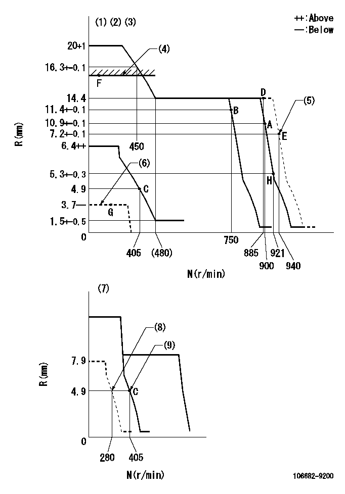
N:Pump speed
R:Rack position (mm)
(1)Minimum - maximum speed specification
(2)Target notch: K
(3)Tolerance for racks not indicated: +-0.05mm.
(4)RACK LIMIT
(5)Set at delivery
(6)Load lever stop (with the speed lever at full)
(7)Variable speed specification: idling adjustment
(8)Set idle sub-spring
(9)Main spring setting
----------
K=11
----------
----------
K=11
----------
Speed control lever angle
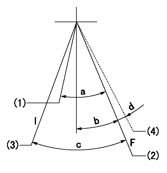
F:Full speed
I:Idle
(1)Set the pump speed at aa
(2)Set the pump speed at bb.
(3)Stopper bolt setting
(4)Set at delivery
----------
aa=750r/min bb=900r/min
----------
a=8deg+-5deg b=6deg+-5deg c=26deg+-5deg d=(1deg)
----------
aa=750r/min bb=900r/min
----------
a=8deg+-5deg b=6deg+-5deg c=26deg+-5deg d=(1deg)
0000000901
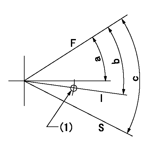
F:Full load
I:Idle
S:Stop
(1)Use the hole at R = aa
----------
aa=27mm
----------
a=26.5deg+-5deg b=34deg+-5deg c=53deg+-5deg
----------
aa=27mm
----------
a=26.5deg+-5deg b=34deg+-5deg c=53deg+-5deg
Timing setting
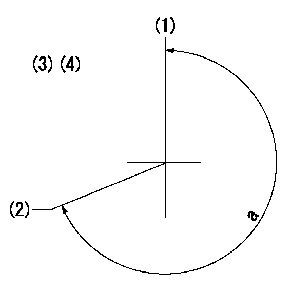
(1)Pump vertical direction
(2)Coupling's key groove position at No 1 cylinder's beginning of injection
(3)-
(4)-
----------
----------
a=(260deg)
----------
----------
a=(260deg)
Information:
Outside Leaks
Possible Causes/Corrections Leaks In Hoses Or ConnectionsCheck all hoses and connections for visual signs of leakage. If no leaks are seen, look for damage to hoses or loose clamps. Leaks In The Radiator And/Or Expansion TankPut pressure to the radiator and/or expansion tank with the 9S8140 Cooling System Pressurizing Pump Group and check for leaks. Leaks In The HeaterPut pressure to the cooling system with the 9S8140 Cooling System Pressurizing Pump Group and check the heater for leaks. Leaks In The Water PumpCheck the water pump for leaks before starting the engine, then start the engine and look for leaks. If there are leaks at the water pump, repair or install a new water pump. Cylinder Head Gasket LeakageLook for leaks along the surface of the cylinder head gasket. If you see leaks, install a new head gasket.Coolant Leaks At The Overflow Tube
Possible Causes/Corrections Defective Pressure Cap Or Relief ValveCheck the sealing surfaces of the pressure cap and the radiator to be sure the cap is sealing correctly. Check the opening pressure and sealing ability of the pressure cap or relief valve with the 9S8140 Cooling System Pressurizing Pump Group. Engine Runs Too HotIf coolant temperature is too high, pressure will be high enough to move the cap off of the sealing surface in the radiator and cause coolant loss through the overflow tube. See "Overheating" in Cooling System Troubleshooting Section. Expansion Tank Too Small Or Installed WrongThe expansion tank can be either a part of the radiator or it can be installed separately from the radiator. The expansion tank must be large enough to hold the expansion of the coolant as it gets warm or has sudden changes in pressure. Make sure the expansion tank is installed correctly, and the size is according to the recommendations of the truck manufacturer. Cylinder Head Gasket Leakage Or Crack(s) In Cylinder Head Or Cylinder BlockRemove the radiator cap and, with the engine running, look for air bubbles in the coolant. Bubbles in the coolant are a sign of probable leakage at the head gasket. Remove the cylinder head from the engine. Check cylinder head, cylinder walls and head gasket surface of the cylinder block for cracks. When the head is installed, use a new head gasket, spacer plate gasket, water seals, and O-ring seals.Inside Leakage
Possible Causes/Corrections Cylinder Head Gasket LeakageIf the cylinder head gasket leaks between a water passage and an opening into the crankcase, coolant will get into the crankcase. Crack(s) In Cylinder HeadCrack(s) in the upper surface of the cylinder head, or an area between a water passage and an opening into the crankcase, can allow coolant to get into the crankcase. Crack(s) In Cylinder BlockCrack(s) in the cylinder block between a water passage and the crankcase will let coolant get into the crankcase.