Information injection-pump assembly
BOSCH
9 400 617 600
9400617600
ZEXEL
106682-9120
1066829120
MITSUBISHI-HEAV
35A6500340
35a6500340

Rating:
Service parts 106682-9120 INJECTION-PUMP ASSEMBLY:
1.
_
5.
AUTOM. ADVANCE MECHANIS
8.
_
9.
_
11.
Nozzle and Holder
35A6100010
12.
Open Pre:MPa(Kqf/cm2)
21.6{220}
15.
NOZZLE SET
Include in #1:
106682-9120
as INJECTION-PUMP ASSEMBLY
Cross reference number
BOSCH
9 400 617 600
9400617600
ZEXEL
106682-9120
1066829120
MITSUBISHI-HEAV
35A6500340
35a6500340
Zexel num
Bosch num
Firm num
Name
106682-9120
9 400 617 600
35A6500340 MITSUBISHI-HEAV
INJECTION-PUMP ASSEMBLY
S6A3 K
S6A3 K
Calibration Data:
Adjustment conditions
Test oil
1404 Test oil ISO4113 or {SAEJ967d}
1404 Test oil ISO4113 or {SAEJ967d}
Test oil temperature
degC
40
40
45
Nozzle and nozzle holder
105780-8130
Bosch type code
EFEP215A
Nozzle
105780-0050
Bosch type code
DN6TD119NP1T
Nozzle holder
105780-2090
Bosch type code
EFEP215
Opening pressure
MPa
17.2
Opening pressure
kgf/cm2
175
Injection pipe
Outer diameter - inner diameter - length (mm) mm 8-4-1000
Outer diameter - inner diameter - length (mm) mm 8-4-1000
Overflow valve
131424-3420
Overflow valve opening pressure
kPa
255
221
289
Overflow valve opening pressure
kgf/cm2
2.6
2.25
2.95
Tester oil delivery pressure
kPa
157
157
157
Tester oil delivery pressure
kgf/cm2
1.6
1.6
1.6
Direction of rotation (viewed from drive side)
Left L
Left L
Injection timing adjustment
Direction of rotation (viewed from drive side)
Left L
Left L
Injection order
1-5-3-6-
2-4
Pre-stroke
mm
2.8
2.75
2.85
Rack position
Point A R=A
Point A R=A
Beginning of injection position
Governor side NO.1
Governor side NO.1
Difference between angles 1
Cal 1-5 deg. 60 59.5 60.5
Cal 1-5 deg. 60 59.5 60.5
Difference between angles 2
Cal 1-3 deg. 120 119.5 120.5
Cal 1-3 deg. 120 119.5 120.5
Difference between angles 3
Cal 1-6 deg. 180 179.5 180.5
Cal 1-6 deg. 180 179.5 180.5
Difference between angles 4
Cyl.1-2 deg. 240 239.5 240.5
Cyl.1-2 deg. 240 239.5 240.5
Difference between angles 5
Cal 1-4 deg. 300 299.5 300.5
Cal 1-4 deg. 300 299.5 300.5
Injection quantity adjustment
Adjusting point
A
Rack position
15.3
Pump speed
r/min
900
900
900
Average injection quantity
mm3/st.
553
544
562
Max. variation between cylinders
%
0
-3
3
Basic
*
Fixing the lever
*
Injection quantity adjustment_02
Adjusting point
B
Rack position
6.6+-0.5
Pump speed
r/min
250
250
250
Average injection quantity
mm3/st.
25
22
28
Max. variation between cylinders
%
0
-10
10
Fixing the rack
*
Test data Ex:
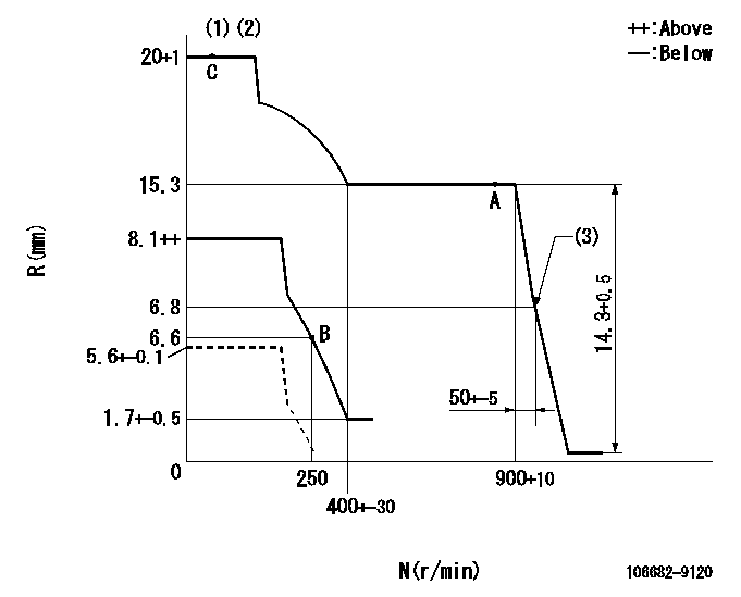
Governor adjustment

N:Pump speed
R:Rack position (mm)
(1)Maximum - minimum speed specification (using speed lever at adjustment)
(2)Target notch: K
(3)Idle sub spring setting: L1.
----------
K=12 L1=6.8-0.5mm
----------
----------
K=12 L1=6.8-0.5mm
----------
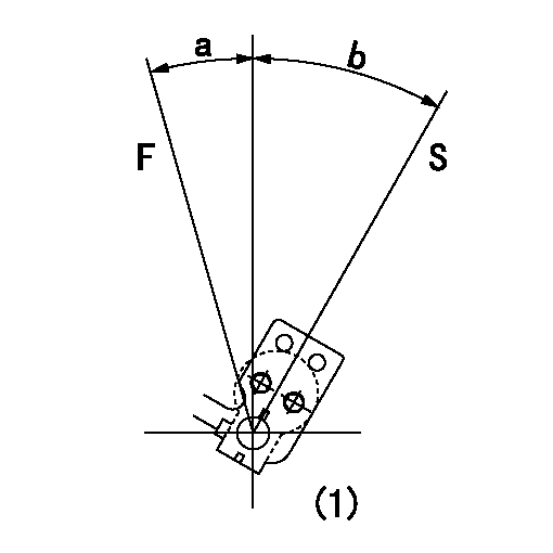
Speed control lever angle

F:Full speed
S:Stop
(1)At the center of the lever key groove
----------
----------
a=17.5deg+-5deg b=33deg+-3deg
----------
----------
a=17.5deg+-5deg b=33deg+-3deg
0000000901

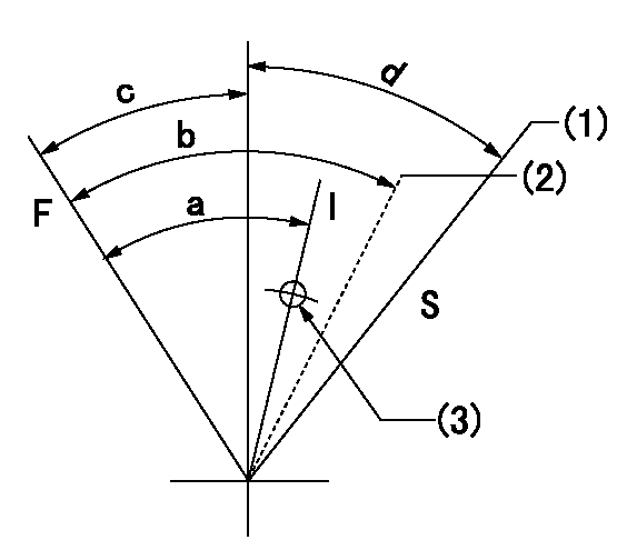
F:Full load
I:Idle
S:Stop
(1)Stop side boss position
(2)Pump speed aa, rack position bb
(3)Use the screw above R = cc
----------
aa=0r/min bb=5.6+-0.1mm cc=60mm
----------
a=29deg+-5deg b=(40deg)+-5deg c=19deg+-5deg d=30deg+-5deg
----------
aa=0r/min bb=5.6+-0.1mm cc=60mm
----------
a=29deg+-5deg b=(40deg)+-5deg c=19deg+-5deg d=30deg+-5deg
Timing setting

(1)Pump vertical direction
(2)Coupling's key groove position at No 1 cylinder's beginning of injection
(3)-
(4)-
----------
----------
a=(20deg)
----------
----------
a=(20deg)
Information:
Illustration 2 g03507406
Typical example of the 456-6048 DPF TOOL GP
Use the following procedure to measure the amount of ash in the DPF:
Use a wire with the maximum diameter of 1.04140 mm (0.041 inch) or the 456-6048 DPF TOOL GP. Hold the wire or tool so that the end of the wire is just inside the cell approximately 6.35000 mm (0.25 inch).
Drop the wire into the cell of the DPF.
Mark the wire at the top of the cell where the wire exits from the DPF.
Measure the depth that the wire dropped by measuring from the mark to the bottom tip of the wire.
Record the measurement.
Illustration 3 g03021156
Top view of DPF
View of locations for recording measurements
(1) Weld line
Perform Steps 7.b through 7.e for all locations. Refer to Illustration 3 for the proper location for recording measurements.
Average the measurements and refer to Table 3 for the acceptable measurements.
Table 3
Filter Assembly Part Number New Service Kit Part Number Reman Service Kit Part Number - Upgrade to New Reman Service Kit Part Number - Cat Factory Cleaned Measured Wire Depth Requires Cleaning Acceptable Cleaned Measured Wire Depth
358-3658 358-3659 20R-0696 20R-5620 Less than 178 mm (7 inch) Greater than 279 mm (11 inch)
358-3661 358-3662 20R-0697 20R-5621 Less than 203 mm (8 inch) Greater than 305 mm (12 inch)
358-3663 358-3664 20R-0698 20R-5622 Less than 203 mm (8 inch) Greater than 305 mm (12 inch)
358-3666 358-3667 20R-0699 20R-5623 Less than 254 mm (10 inch) Greater than 343 mm (13.5 inch)
358-3668 358-3669 20R-0700 20R-5624 Less than 279 mm (11 inch) Greater than 394 mm (15.5 inch)
The DPF is ready to be returned to service. DPF Ash Service
Purpose
The engine ash model must be reset whenever the filter is cleaned or replaced. Reseting the ash model places the DPF ash volume back to the "Clean State". The resetting will allow the regeneration of the DPF to function properly. Cat ET Location
Connect to Cat ET.
Illustration 4 g02477962
Select "Service" from the top menu and highlight "Service Procedures".
Illustration 5 g02477961
From the "Service Procedures" menu, highlight "DPF Ash Service". Select "Start".
Illustration 6 g02495621
Illustration 7 g02477958
Select "Ash Service Reset" to start the test procedure.
Illustration 8 g02477960
Choose the correct replacement type of diesel particulate filter in the menu that appears. The types of replacements for the diesel particulate filter are the following:
"Field cleaned" A filter that has been cleaned and reapplied
"New" - A new filter replacement
"Remanufactured" - A remanufactured filter replacement
Illustration 9 g02495643
Illustration 10 g02478024
Once the reset is completed, a log of the reset is captured and visible as a new row of information in the DPF ash service screen.
Perform a "Manual DPF Regeneration" with Cat ET to reset the soot level
Have questions with 106682-9120?
Group cross 106682-9120 ZEXEL
Komatsu
Komatsu
Mitsubishi-Heav
106682-9120
9 400 617 600
35A6500340
INJECTION-PUMP ASSEMBLY
S6A3
S6A3