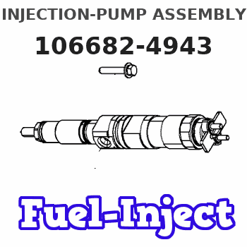
Information injection-pump assembly
BOSCH
9 400 613 391
9400613391
ZEXEL
106682-4943
1066824943
KOMATSU
6215751114
6215751114

Rating:
Service parts 106682-4943 INJECTION-PUMP ASSEMBLY:
1.
_
5.
AUTOM. ADVANCE MECHANIS
7.
COUPLING PLATE
8.
_
9.
_
11.
Nozzle and Holder
12.
Open Pre:MPa(Kqf/cm2)
24.5{250}
15.
NOZZLE SET
Include in #1:
106682-4943
as INJECTION-PUMP ASSEMBLY
Cross reference number
Zexel num
Bosch num
Firm num
Name
106682-4943
9 400 613 391
6215751114 KOMATSU
INJECTION-PUMP ASSEMBLY
12M140 K 14CA INJECTION PUMP ASSY PE6P,6PD PE
12M140 K 14CA INJECTION PUMP ASSY PE6P,6PD PE
Information:
Keep all parts clean from contaminants. Contaminants put into the system may cause rapid wear and shortened component life.
1. Remove the carbon ring and lip from the inner surface of the cylinder liner. 2. Turn the crankshaft until two of the pistons are at bottom center. Remove the nuts and bolts (1) from the connecting rods that are at bottom center. Remove connecting rod caps (2), and put identification marks on them for installation purposes.
Do not let the connecting rods hit the crankshaft or the bottom edge of the cylinder liners when the pistons are removed.
3. Push the connecting rods and pistons away from the crankshaft until the piston rings are out of the cylinder liners. Remove the two pistons from the engine.4. Keep each connecting rod cap with its respective connecting rod and piston. Put identification marks on each piston as to its location in the engine.5. Do Steps 1 through 4 for the removal of the remaining pistons.Install Pistons And Connecting Rods
1. Turn the crankshaft until the bearing journals for the pistons to be installed are at bottom center.2. Put clean engine oil on the crankshaft journals and on the inside of the cylinder liners. Put clean engine oil on the piston rings and the connecting rod bearings.3. Move the piston rings on the pistons until the ring openings are approximately 90° apart. 4. Put the piston in the cylinder liner with the "V" mark on the piston in alignment with the "V" mark on the cylinder block. Put tooling (A) in position on the cylinder block and compress the piston rings.5. Push the piston into the cylinder liner and out of the ring compressor. 6. Pull the connecting rod into position on the crankshaft as shown. Install connecting rod bolts (1) in the connecting rods.7. Put clean engine oil on the lower half of the connecting rod bearing. Put 2P2506 Thread Lubricant on the bolt threads and on the surfaces of the nuts that make contact with the rod caps.
When the connecting rod caps are installed, make sure the number on the side of the cap is next to and respective with the number on the side of the connecting rod.
8. Install connecting rod caps (2) and the nuts that hold them. Tighten the nuts to a torque of 41 4 N m (30 3 lb ft). Put a mark on each nut as to its location, and tighten them 90° 5° more.9. Perform Steps 1 through 8 for the remainder of the pistons.End By:a. install oil pumpb. install oil pan platec. install spacer plate
Perform Scheduled Oil Sampling on oil wetted compartments after performing service work to check for contaminants left in the system following repair. Contaminants put into the system may cause rapid wear and shortened component life.
Disassemble Pistons And Connecting Rods
Start By:a. remove pistons and connecting rods
Keep all parts clean from contaminants. Contaminants put into the system may cause rapid wear and shortened component life.
1. Remove the rings from the
Have questions with 106682-4943?
Group cross 106682-4943 ZEXEL
Komatsu
Komatsu
Komatsu
106682-4943
9 400 613 391
6215751114
INJECTION-PUMP ASSEMBLY
12M140
12M140