Information injection-pump assembly
BOSCH
F 019 Z10 432
f019z10432
ZEXEL
106682-4940
1066824940
KOMATSU
6215751110
6215751110
Rating:
Service parts 106682-4940 INJECTION-PUMP ASSEMBLY:
1.
_
5.
AUTOM. ADVANCE MECHANIS
7.
COUPLING PLATE
8.
_
9.
_
11.
Nozzle and Holder
12.
Open Pre:MPa(Kqf/cm2)
24.5(250)
15.
NOZZLE SET
Include in #1:
106682-4940
as INJECTION-PUMP ASSEMBLY
Cross reference number
BOSCH
F 019 Z10 432
f019z10432
ZEXEL
106682-4940
1066824940
KOMATSU
6215751110
6215751110
Zexel num
Bosch num
Firm num
Name
Calibration Data:
Adjustment conditions
Test oil
1404 Test oil ISO4113 or {SAEJ967d}
1404 Test oil ISO4113 or {SAEJ967d}
Test oil temperature
degC
40
40
45
Nozzle and nozzle holder
105780-8130
Bosch type code
EFEP215A
Nozzle
105780-0050
Bosch type code
DN6TD119NP1T
Nozzle holder
105780-2090
Bosch type code
EFEP215
Opening pressure
MPa
17.2
Opening pressure
kgf/cm2
175
Injection pipe
Outer diameter - inner diameter - length (mm) mm 8-4-1000
Outer diameter - inner diameter - length (mm) mm 8-4-1000
Overflow valve
131425-1620
Overflow valve opening pressure
kPa
255
255
255
Overflow valve opening pressure
kgf/cm2
2.6
2.6
2.6
Tester oil delivery pressure
kPa
157
157
157
Tester oil delivery pressure
kgf/cm2
1.6
1.6
1.6
Direction of rotation (viewed from drive side)
Right R
Right R
Injection timing adjustment
Direction of rotation (viewed from drive side)
Right R
Right R
Injection order
1-5-3-6-
2-4
Pre-stroke
mm
2.8
2.75
2.85
Beginning of injection position
Drive side NO.1
Drive side NO.1
Difference between angles 1
Cal 1-5 deg. 60 59.5 60.5
Cal 1-5 deg. 60 59.5 60.5
Difference between angles 2
Cal 1-3 deg. 120 119.5 120.5
Cal 1-3 deg. 120 119.5 120.5
Difference between angles 3
Cal 1-6 deg. 180 179.5 180.5
Cal 1-6 deg. 180 179.5 180.5
Difference between angles 4
Cyl.1-2 deg. 240 239.5 240.5
Cyl.1-2 deg. 240 239.5 240.5
Difference between angles 5
Cal 1-4 deg. 300 299.5 300.5
Cal 1-4 deg. 300 299.5 300.5
Injection quantity adjustment
Adjusting point
A
Rack position
17.1
Pump speed
r/min
1050
1050
1050
Average injection quantity
mm3/st.
447
443.5
450.5
Max. variation between cylinders
%
0
-3
3
Basic
*
Fixing the lever
*
Boost pressure
kPa
53.3
53.3
Boost pressure
mmHg
400
400
Remarks
Standard point A's rack position same as row R
Standard point A's rack position same as row R
Injection quantity adjustment_02
Adjusting point
-
Rack position
8.8+-0.5
Pump speed
r/min
325
325
325
Average injection quantity
mm3/st.
20
18.5
21.5
Max. variation between cylinders
%
0
-15
15
Fixing the rack
*
Boost pressure
kPa
0
0
0
Boost pressure
mmHg
0
0
0
Remarks
Adjust only variation between cylinders; adjust governor according to governor specifications.
Adjust only variation between cylinders; adjust governor according to governor specifications.
Boost compensator adjustment
Pump speed
r/min
600
600
600
Rack position
R1-2
Boost pressure
kPa
6.7
4
9.4
Boost pressure
mmHg
50
30
70
Boost compensator adjustment_02
Pump speed
r/min
600
600
600
Rack position
R1(17.1)
Boost pressure
kPa
40
33.3
46.7
Boost pressure
mmHg
300
250
350
Test data Ex:
Governor adjustment
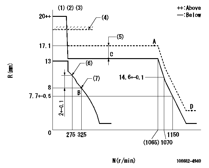
N:Pump speed
R:Rack position (mm)
(1)Target notch: K
(2)Tolerance for racks not indicated: +-0.05mm.
(3)The torque control spring does not operate.
(4)Rack limit for 106684-4080;RAL
(5)Boost compensator stroke: BCL
(6)Set the No 1 idle sub spring.
(7)Set the 2nd idle sub spring.
----------
K=10 RAL=17.6+0.2mm BCL=2+-0.1mm
----------
----------
K=10 RAL=17.6+0.2mm BCL=2+-0.1mm
----------
Speed control lever angle

F:Full speed
I:Idle
(1)Stopper bolt setting
----------
----------
a=5deg+-5deg b=27deg+-5deg
----------
----------
a=5deg+-5deg b=27deg+-5deg
Stop lever angle
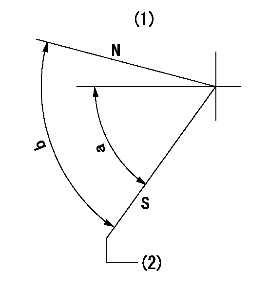
N:Pump normal
S:Stop the pump.
(1)No return spring
(2)Pump speed aa and rack position bb (to be sealed at delivery)
----------
aa=0r/min bb=1-0.5mm
----------
a=63deg+-5deg b=(73deg)
----------
aa=0r/min bb=1-0.5mm
----------
a=63deg+-5deg b=(73deg)
Timing setting

(1)Pump vertical direction
(2)Coupling's key groove position at No 1 cylinder's beginning of injection
(3)-
(4)-
----------
----------
a=(30deg)
----------
----------
a=(30deg)
Information:
Keep all parts clean from contaminants. Contaminants put into the system may cause rapid wear and shortened component life.
1. Remove water seals (3), O-ring seal (1) and spacer plate (2).
Do not damage the dowels as the spacer plate is removed.
2. Remove O-ring seal (5) and spacer plate gasket (4). The following steps are to install the spacer plate.3. Thoroughly clean the spacer plate and the cylinder block surface.4. Install new spacer plate gasket (4) and new O-ring seal (5). If dowel in block has been removed for any reason, the overall installation height is 16.0 5 mm (.630 .020 in).5. Install spacer plate (2). Both surfaces of spacer plate, top of cylinder block and both sides of spacer plate gasket must be clean and dry. Do not use any gasket adhesive or other substances on these surfaces.6. Install a new O-ring seal (1).7. Install new water seals (3).8. Check the cylinder liner projection. See the topic, Install Cylinder Liners, in this manual.End By:a. install cylinder head
Perform Scheduled Oil Sampling on oil wetted compartments after performing service work to check for contaminants left in the system following repair. Contaminants put into the system may cause rapid wear and shortened component life.