Information injection-pump assembly
BOSCH
9 400 617 553
9400617553
ZEXEL
106682-4450
1066824450
KUBOTA
1452617200
1452617200
Rating:
Service parts 106682-4450 INJECTION-PUMP ASSEMBLY:
1.
_
5.
AUTOM. ADVANCE MECHANIS
7.
COUPLING PLATE
8.
_
9.
_
11.
Nozzle and Holder
12.
Open Pre:MPa(Kqf/cm2)
26.0(265)
15.
NOZZLE SET
Include in #1:
106682-4450
as INJECTION-PUMP ASSEMBLY
Cross reference number
BOSCH
9 400 617 553
9400617553
ZEXEL
106682-4450
1066824450
KUBOTA
1452617200
1452617200
Zexel num
Bosch num
Firm num
Name
106682-4450
9 400 617 553
1452617200 KUBOTA
INJECTION-PUMP ASSEMBLY
LH105CS * K
LH105CS * K
Calibration Data:
Adjustment conditions
Test oil
1404 Test oil ISO4113 or {SAEJ967d}
1404 Test oil ISO4113 or {SAEJ967d}
Test oil temperature
degC
40
40
45
Nozzle and nozzle holder
105780-8130
Bosch type code
EFEP215A
Nozzle
105780-0050
Bosch type code
DN6TD119NP1T
Nozzle holder
105780-2090
Bosch type code
EFEP215
Opening pressure
MPa
17.2
Opening pressure
kgf/cm2
175
Injection pipe
Outer diameter - inner diameter - length (mm) mm 8-3-600
Outer diameter - inner diameter - length (mm) mm 8-3-600
Overflow valve
132424-0620
Overflow valve opening pressure
kPa
157
123
191
Overflow valve opening pressure
kgf/cm2
1.6
1.25
1.95
Tester oil delivery pressure
kPa
157
157
157
Tester oil delivery pressure
kgf/cm2
1.6
1.6
1.6
Direction of rotation (viewed from drive side)
Left L
Left L
Injection timing adjustment
Direction of rotation (viewed from drive side)
Left L
Left L
Injection order
1-4-2-6-
3-5
Pre-stroke
mm
3
2.95
3.05
Beginning of injection position
Drive side NO.1
Drive side NO.1
Difference between angles 1
Cal 1-4 deg. 60 59.5 60.5
Cal 1-4 deg. 60 59.5 60.5
Difference between angles 2
Cyl.1-2 deg. 120 119.5 120.5
Cyl.1-2 deg. 120 119.5 120.5
Difference between angles 3
Cal 1-6 deg. 180 179.5 180.5
Cal 1-6 deg. 180 179.5 180.5
Difference between angles 4
Cal 1-3 deg. 240 239.5 240.5
Cal 1-3 deg. 240 239.5 240.5
Difference between angles 5
Cal 1-5 deg. 300 299.5 300.5
Cal 1-5 deg. 300 299.5 300.5
Injection quantity adjustment
Adjusting point
A
Rack position
11.6
Pump speed
r/min
900
900
900
Each cylinder's injection qty
mm3/st.
265
259.1
270.9
Basic
*
Fixing the rack
*
Injection quantity adjustment_02
Adjusting point
B
Rack position
6+-0.5
Pump speed
r/min
300
300
300
Each cylinder's injection qty
mm3/st.
30
25.5
34.5
Fixing the rack
*
Test data Ex:
Governor adjustment
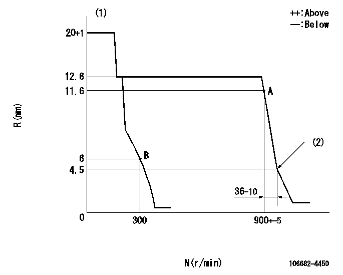
N:Pump speed
R:Rack position (mm)
(1)Target notch: K
(2)Idle sub spring setting: L1.
----------
K=14 L1=4.5-0.5mm
----------
----------
K=14 L1=4.5-0.5mm
----------
Speed control lever angle

F:Full speed
I:Idle
S:Stop
----------
----------
a=18deg+-5deg b=32deg+-5deg c=33deg+-5deg
----------
----------
a=18deg+-5deg b=32deg+-5deg c=33deg+-5deg
Stop lever angle

N:Pump normal
S:Stop the pump.
----------
----------
a=(0deg) b=(53deg)
----------
----------
a=(0deg) b=(53deg)
Timing setting

(1)Pump vertical direction
(2)Coupling's key groove position at No 1 cylinder's beginning of injection
(3)-
(4)-
----------
----------
a=(40deg)
----------
----------
a=(40deg)
Information:
Recommended Procedure
1. Air in Fuel System ... With air in the fuel system the engine will normally be difficult to start, run rough and release a large amount of white smoke. To remove the air from the fuel system, open the manual bleed valve on the fuel injection pump housing. Operate the priming pump until the flow of fuel from the manual bleed valve is free of air. Close the manual bleed valve and fasten the fuel priming pump. Start the engine. If the engine still does not run smooth or releases a large amount of white smoke, loosen the fuel line nuts one at a time at the cylinder heads, and permit the fuel to come out until it is free of air. Tighten the fuel line nuts. If air is not removed in this way, put 35 kPa (5 psi) of air pressure to the fuel tank.
Do not use more than 55 kPa (8 psi) of air pressure in the fuel tank or damage to the tank may result.
Check for leaks at the connections between the fuel tank and the fuel transfer pump. If leaks are found, tighten the connections or replace the lines. If there are no visual leaks, remove the fuel supply line from the tank and connect it to an outside fuel supply. If this corrects the problem, the suction line (standpipe) inside the fuel tank has a leak.2. Valve Adjustment Not Correct ... Check and make necessary adjustments as per Testing and Adjusting Section of this Service Manual. Intake valve clearance is 0.38 mm (.015 in) and exhaust valve clearance is 0.64 mm (.025 in). Also check for a bent or broken push rod.3. Fuel Injection Timing Not Correct ... Check and make necessary adjustments as per Testing and Adjusting Section of this Service Manual.4. Automatic Timing Advance Does Not Operate Correctly ... Check with engine warm. Use the 8T5300 Timing Indicator Group to check the automatic timing advance unit. Check to see that the advance is smooth and that the amount of advance is correct. See Fuel System of the Testing and Adjusting section of this Service Manual for the subject Checking Engine Timing And Automatic Timing Advance Unit With 8T5300 Timing Indicator Group. If the timing indicator is not available, make rapid "acceleration" (increase in speed) from low idle to high idle. Engine must have smooth acceleration.A timing advance that does not operate correctly can cause delays of the engine acceleration at some rpm before high idle, or possibly cause the engine to run rough and have exhaust noise (backfire) during acceleration. This condition is difficult to find if engine acceleration is slow or at a constant engine rpm.5. Bad Fuel Nozzle(s) ... Find a bad nozzle by running engine at the rpm where it runs rough. Loosen the fuel line nut at the cylinder head enough to stop fuel supply to that cylinder. Each cylinder must be checked this way. If a cylinder is found where loosening of
Have questions with 106682-4450?
Group cross 106682-4450 ZEXEL
Komatsu
Komatsu
Komatsu
Komatsu
Komatsu
Kubota
106682-4450
9 400 617 553
1452617200
INJECTION-PUMP ASSEMBLY
LH105CS
LH105CS