Information injection-pump assembly
ZEXEL
106682-4440
1066824440
KOMATSU
6215711130
6215711130
Rating:
Cross reference number
ZEXEL
106682-4440
1066824440
KOMATSU
6215711130
6215711130
Zexel num
Bosch num
Firm num
Name
Calibration Data:
Adjustment conditions
Test oil
1404 Test oil ISO4113 or {SAEJ967d}
1404 Test oil ISO4113 or {SAEJ967d}
Test oil temperature
degC
40
40
45
Nozzle and nozzle holder
105780-8130
Bosch type code
EFEP215A
Nozzle
105780-0050
Bosch type code
DN6TD119NP1T
Nozzle holder
105780-2090
Bosch type code
EFEP215
Opening pressure
MPa
17.2
Opening pressure
kgf/cm2
175
Injection pipe
Outer diameter - inner diameter - length (mm) mm 8-3-600
Outer diameter - inner diameter - length (mm) mm 8-3-600
Overflow valve
131424-7120
Overflow valve opening pressure
kPa
255
221
289
Overflow valve opening pressure
kgf/cm2
2.6
2.25
2.95
Tester oil delivery pressure
kPa
157
157
157
Tester oil delivery pressure
kgf/cm2
1.6
1.6
1.6
Direction of rotation (viewed from drive side)
Right R
Right R
Injection timing adjustment
Direction of rotation (viewed from drive side)
Right R
Right R
Injection order
1-5-3-6-
2-4
Pre-stroke
mm
3.5
3.45
3.55
Beginning of injection position
Drive side NO.1
Drive side NO.1
Difference between angles 1
Cal 1-5 deg. 60 59.5 60.5
Cal 1-5 deg. 60 59.5 60.5
Difference between angles 2
Cal 1-3 deg. 120 119.5 120.5
Cal 1-3 deg. 120 119.5 120.5
Difference between angles 3
Cal 1-6 deg. 180 179.5 180.5
Cal 1-6 deg. 180 179.5 180.5
Difference between angles 4
Cyl.1-2 deg. 240 239.5 240.5
Cyl.1-2 deg. 240 239.5 240.5
Difference between angles 5
Cal 1-4 deg. 300 299.5 300.5
Cal 1-4 deg. 300 299.5 300.5
Injection quantity adjustment
Adjusting point
A
Rack position
13
Pump speed
r/min
1000
1000
1000
Average injection quantity
mm3/st.
282
280
284
Max. variation between cylinders
%
0
-3
3
Basic
*
Fixing the lever
*
Boost pressure
kPa
53.3
53.3
Boost pressure
mmHg
400
400
Remarks
Standard point A's rack position same as 106684-4010 in row R
Standard point A's rack position same as 106684-4010 in row R
Injection quantity adjustment_02
Adjusting point
C
Rack position
7.8+-0.5
Pump speed
r/min
325
325
325
Average injection quantity
mm3/st.
16.5
15
18
Max. variation between cylinders
%
0
-15
15
Fixing the rack
*
Boost pressure
kPa
0
0
0
Boost pressure
mmHg
0
0
0
Boost compensator adjustment
Pump speed
r/min
600
600
600
Rack position
12.4
Boost pressure
kPa
6.7
4
9.4
Boost pressure
mmHg
50
30
70
Boost compensator adjustment_02
Pump speed
r/min
600
600
600
Rack position
14.4
Boost pressure
kPa
40
33.3
46.7
Boost pressure
mmHg
300
250
350
Test data Ex:
Governor adjustment
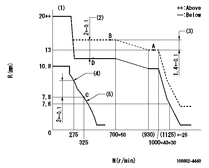
N:Pump speed
R:Rack position (mm)
(1)Notch fixed: K
(2)Boost compensator stroke
(3)Rack difference between N = N1 and N = N2
(4)Set the No 1 idle sub spring.
(5)Set the 2nd idle sub spring.
----------
K=20 N1=1000r/min N2=700r/min
----------
----------
K=20 N1=1000r/min N2=700r/min
----------
Speed control lever angle
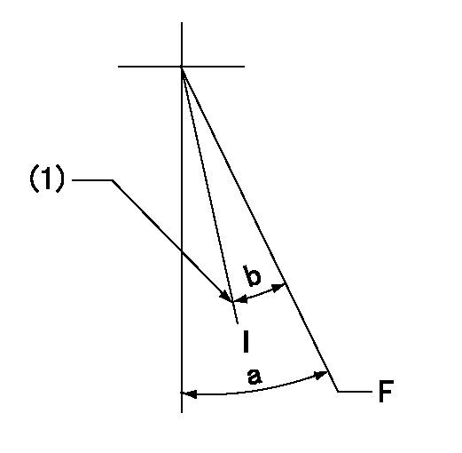
F:Full speed
I:Idle
(1)Stopper bolt setting
----------
----------
a=(32deg)+-5deg b=(26deg)+-5deg
----------
----------
a=(32deg)+-5deg b=(26deg)+-5deg
Stop lever angle
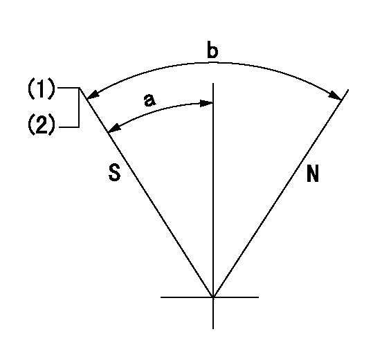
N:Pump normal
S:Stop the pump.
(1)Pump speed aa, rack position bb
(2)(Seal at delivery.)
----------
aa=0r/min bb=1-0.2mm
----------
a=33deg+-5deg b=(73deg)
----------
aa=0r/min bb=1-0.2mm
----------
a=33deg+-5deg b=(73deg)
Timing setting

(1)Pump vertical direction
(2)Coupling's key groove position at No 1 cylinder's beginning of injection
(3)-
(4)-
----------
----------
a=(30deg)
----------
----------
a=(30deg)
Information:
This troubleshooting guide, when followed exactly as shown, can be an aid for the serviceman to find the cause of existing problems. The information from the measurements will also show proof if there is any basis for the complaint.Be sure to get a good description of the problem from the operator and/or the person who owns the vehicle. What they tell you about the problem can save you time and make the repair job faster and easier.Low Power And High Fuel Consumption Problems
The troubleshooting charts that follow provide a definite sequence to be followed for a logical, one by one elimination of many variables. The encircled numbers do not designate steps, but are references to detailed instructions that can not be shown on the chart. Always read the written material that corresponds with the encircled numbers on the charts.The Primary Engine Tests consist of quick and easy procedures that could identify the problem with a minimum loss of time. Always make these tests before starting the more involved troubleshooting charts.The necessary instruments to check each problem in sequence are shown on the chart. If the correct instrument is not available for the test, do not continue. The vehicle must be sent to a shop where the necessary tools are available.Whenever a problem is found and corrected, always run the test again to that point to be sure there is not a combination of problems. When the problem has been corrected and the complaint resolved, stop the test. Do not continue through the complete procedure just because it is there.When investigating possible causes, follow the letter sequence shown. Possible causes are arranged in order from more probable/easiest to check to less probable/more complex to check.Other Problems: Vehicle Or Vehicle Operation, Misfiring And Running Rough, Too Much Exhaust Smoke, Difficult Starting, Cooling System, Loss Of Coolant, Or Fuel In Crankcase Oil.
The probable causes of a problem are given in the order they most commonly take place. Check the probable causes in the same order that they are given. When troubleshooting, use the section on recommended procedures which follow each chart to check and make the necessary corrections for each probable cause.Engine Vibration Problem
The troubleshooting chart provides a definite sequence to be followed for a logical procedure to determine the frequency and amplitude of vibration so that the source of the vibration can be located and corrected.