Information injection-pump assembly
BOSCH
9 400 617 545
9400617545
ZEXEL
106682-4290
1066824290
KUBOTA
1452610210
1452610210
Rating:
Service parts 106682-4290 INJECTION-PUMP ASSEMBLY:
1.
_
5.
AUTOM. ADVANCE MECHANIS
6.
COUPLING PLATE
7.
COUPLING PLATE
8.
_
9.
_
11.
Nozzle and Holder
12.
Open Pre:MPa(Kqf/cm2)
26.0{265}
15.
NOZZLE SET
Include in #1:
106682-4290
as INJECTION-PUMP ASSEMBLY
Cross reference number
BOSCH
9 400 617 545
9400617545
ZEXEL
106682-4290
1066824290
KUBOTA
1452610210
1452610210
Zexel num
Bosch num
Firm num
Name
106682-4290
9 400 617 545
1452610210 KUBOTA
INJECTION-PUMP ASSEMBLY
LH105CS * K 14CA INJECTION PUMP ASSY PE6P,6PD PE
LH105CS * K 14CA INJECTION PUMP ASSY PE6P,6PD PE
Calibration Data:
Adjustment conditions
Test oil
1404 Test oil ISO4113 or {SAEJ967d}
1404 Test oil ISO4113 or {SAEJ967d}
Test oil temperature
degC
40
40
45
Nozzle and nozzle holder
105780-8130
Bosch type code
EFEP215A
Nozzle
105780-0050
Bosch type code
DN6TD119NP1T
Nozzle holder
105780-2090
Bosch type code
EFEP215
Opening pressure
MPa
17.2
Opening pressure
kgf/cm2
175
Injection pipe
Outer diameter - inner diameter - length (mm) mm 8-3-600
Outer diameter - inner diameter - length (mm) mm 8-3-600
Overflow valve opening pressure
kPa
157
123
191
Overflow valve opening pressure
kgf/cm2
1.6
1.25
1.95
Tester oil delivery pressure
kPa
157
157
157
Tester oil delivery pressure
kgf/cm2
1.6
1.6
1.6
Direction of rotation (viewed from drive side)
Right R
Right R
Injection timing adjustment
Direction of rotation (viewed from drive side)
Right R
Right R
Injection order
1-5-3-6-
2-4
Pre-stroke
mm
3
2.95
3.05
Beginning of injection position
Drive side NO.1
Drive side NO.1
Difference between angles 1
Cal 1-5 deg. 60 59.5 60.5
Cal 1-5 deg. 60 59.5 60.5
Difference between angles 2
Cal 1-3 deg. 120 119.5 120.5
Cal 1-3 deg. 120 119.5 120.5
Difference between angles 3
Cal 1-6 deg. 180 179.5 180.5
Cal 1-6 deg. 180 179.5 180.5
Difference between angles 4
Cyl.1-2 deg. 240 239.5 240.5
Cyl.1-2 deg. 240 239.5 240.5
Difference between angles 5
Cal 1-4 deg. 300 299.5 300.5
Cal 1-4 deg. 300 299.5 300.5
Injection quantity adjustment
Adjusting point
A
Rack position
11.6
Pump speed
r/min
900
900
900
Each cylinder's injection qty
mm3/st.
265
259.1
270.9
Basic
*
Fixing the rack
*
Injection quantity adjustment_02
Adjusting point
B
Rack position
6+-0.5
Pump speed
r/min
300
300
300
Each cylinder's injection qty
mm3/st.
30
25.5
34.5
Fixing the rack
*
Test data Ex:
Governor adjustment
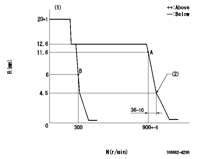
N:Pump speed
R:Rack position (mm)
(1)Target notch: K
(2)Idle sub spring setting: L1.
----------
K=14 L1=4.5-0.5mm
----------
----------
K=14 L1=4.5-0.5mm
----------
Speed control lever angle

F:Full speed
I:Idle
S:Stop
----------
----------
a=18deg+-5deg b=32deg+-5deg c=33deg+-5deg
----------
----------
a=18deg+-5deg b=32deg+-5deg c=33deg+-5deg
Stop lever angle

N:Pump normal
S:Stop the pump.
----------
----------
a=(0deg) b=(53deg)
----------
----------
a=(0deg) b=(53deg)
Timing setting

(1)Pump vertical direction
(2)Coupling's key groove position at No 1 cylinder's beginning of injection
(3)-
(4)-
----------
----------
a=(40deg)
----------
----------
a=(40deg)
Information:
1. Disconnect the glow plug wires and crankcase ventilation tube. Remove the valve cover. 2. Remove the No. 1 fuel injection line (1) and fuel injection valve (2). 3. Install the adapter (3), rod (4), and dial indicator (5) from tool group (A) in the precombustion chamber.
Tighten adapter (4) finger tight only to prevent damage to the fuel valve seat.
4. Rotate the crankshaft in the direction of engine rotation (counterclockwise as viewed the flywheel end) until the maximum reading is read on the dial indicator and the No. 1 cylinder intake and exhaust valves (6) are both closed. The glow plugs can be removed to ease turning of the crankshaft.5. Zero the dial indicator by moving the indicator up or down in the adapter to position the small hand between the red zero and the black zero. Turn the face of the indicator to align the zero with the large hand. Rotate the crankshaft in reverse rotation approximately 30° and repeat step 4 to verify that dial indicator is properly zeroed. 6. Using the rod (9) and plug (8) from tool group (A), depress the oil pressure speed limiter plunger. Move the governor control arm to the full fuel on position and hold it in that position with wire (7). 7. Install the tube assembly (10) from tool group (B), on No. 1 fuel injection pump and slant it slightly upward. Position a suitable container under the tube to catch fuel. 8. Connect the tank hose (12) to the accessory drive housing as shown.9. Fill the tank with a gallon of clean fuel and pressurize it to 15 psi (1,05 kg/cm2) by using the hand pump. If available shop air can be used to pressurize the tank with the use of a pressure regulator (11).
When using shop air adjust the pressure regulator to 15 psi (1,05 kg/cm2) before connecting hose (12) to the engine.
10. Rotate the crankshaft in reverse rotation approximately 30° from TDC (top dead center). At this point a solid stream of fuel should be coming out of the tube.11. Rotate the crankshaft slowly in normal direction of rotation until the fuel flow from the tube is reduced to 6 to 12 drops per minute. At this point the fuel injection pump plunger closes the bypass port and fuel injection begins.12. The reading on the dial indicator, using the red numbers, should be .109 in. BTC (before top center) which is equal to 13.5° fuel injection pump timing. If the reading is not obtained retiming is required. The chart below converts inches of piston travel into degrees of crankshaft rotation. 13. If the engine is properly timed, remove the timing tools and install the valve cover (see INSTALL VALVE COVER for tightening sequence of the bolts), fuel injection valve and line. Tighten the fuel valve retaining nut to 105 5 lb.ft. (14,5 0,5 mkg). Tighten the fuel line nuts to 30 5 lb. ft. (4,1 0,7 mkg). If engine timing is incorrect
Have questions with 106682-4290?
Group cross 106682-4290 ZEXEL
Kubota
106682-4290
9 400 617 545
1452610210
INJECTION-PUMP ASSEMBLY
LH105CS
LH105CS