Information injection-pump assembly
BOSCH
9 400 617 544
9400617544
ZEXEL
106682-4280
1066824280
KUBOTA
1452603210
1452603210
Rating:
Service parts 106682-4280 INJECTION-PUMP ASSEMBLY:
1.
_
5.
AUTOM. ADVANCE MECHANIS
7.
COUPLING PLATE
8.
_
9.
_
10.
NOZZLE AND HOLDER ASSY
11.
Nozzle and Holder
12.
Open Pre:MPa(Kqf/cm2)
26.0(265)
14.
NOZZLE
15.
NOZZLE SET
Include in #1:
106682-4280
as INJECTION-PUMP ASSEMBLY
Cross reference number
BOSCH
9 400 617 544
9400617544
ZEXEL
106682-4280
1066824280
KUBOTA
1452603210
1452603210
Zexel num
Bosch num
Firm num
Name
106682-4280
9 400 617 544
1452603210 KUBOTA
INJECTION-PUMP ASSEMBLY
LH105CS * K
LH105CS * K
Calibration Data:
Adjustment conditions
Test oil
1404 Test oil ISO4113 or {SAEJ967d}
1404 Test oil ISO4113 or {SAEJ967d}
Test oil temperature
degC
40
40
45
Nozzle and nozzle holder
105780-8130
Bosch type code
EFEP215A
Nozzle
105780-0050
Bosch type code
DN6TD119NP1T
Nozzle holder
105780-2090
Bosch type code
EFEP215
Opening pressure
MPa
17.2
Opening pressure
kgf/cm2
175
Injection pipe
Outer diameter - inner diameter - length (mm) mm 8-3-600
Outer diameter - inner diameter - length (mm) mm 8-3-600
Overflow valve
132424-0620
Overflow valve opening pressure
kPa
157
123
191
Overflow valve opening pressure
kgf/cm2
1.6
1.25
1.95
Tester oil delivery pressure
kPa
157
157
157
Tester oil delivery pressure
kgf/cm2
1.6
1.6
1.6
Direction of rotation (viewed from drive side)
Right R
Right R
Injection timing adjustment
Direction of rotation (viewed from drive side)
Right R
Right R
Injection order
1-5-3-6-
2-4
Pre-stroke
mm
3
2.95
3.05
Beginning of injection position
Drive side NO.1
Drive side NO.1
Difference between angles 1
Cal 1-5 deg. 60 59.5 60.5
Cal 1-5 deg. 60 59.5 60.5
Difference between angles 2
Cal 1-3 deg. 120 119.5 120.5
Cal 1-3 deg. 120 119.5 120.5
Difference between angles 3
Cal 1-6 deg. 180 179.5 180.5
Cal 1-6 deg. 180 179.5 180.5
Difference between angles 4
Cyl.1-2 deg. 240 239.5 240.5
Cyl.1-2 deg. 240 239.5 240.5
Difference between angles 5
Cal 1-4 deg. 300 299.5 300.5
Cal 1-4 deg. 300 299.5 300.5
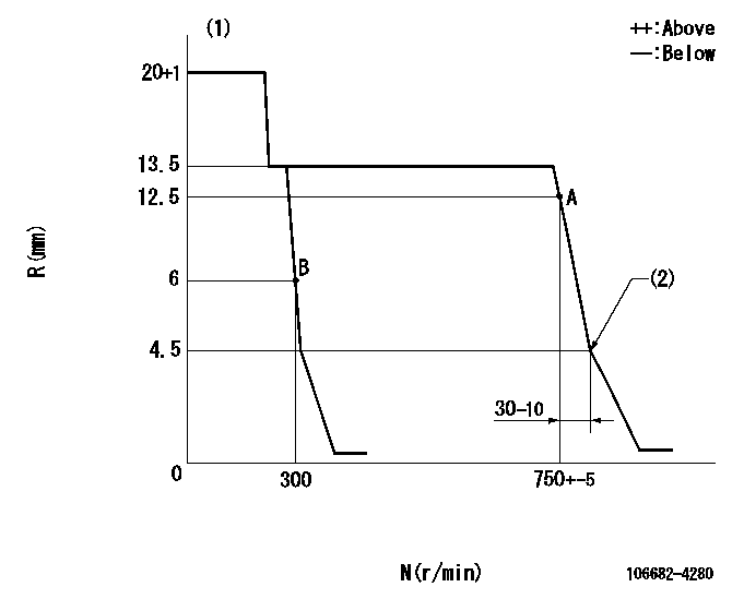
Injection quantity adjustment
Adjusting point
A
Rack position
12.5
Pump speed
r/min
750
750
750
Each cylinder's injection qty
mm3/st.
305
298.3
311.7
Basic
*
Fixing the rack
*
Injection quantity adjustment_02
Adjusting point
B
Rack position
6+-0.5
Pump speed
r/min
300
300
300
Each cylinder's injection qty
mm3/st.
30
25.5
34.5
Fixing the rack
*
Test data Ex:
Governor adjustment
N:Pump speed
R:Rack position (mm)
(1)Target notch: K
(2)Idle sub spring setting: L1.
----------
K=11 L1=4.5-0.5mm
----------
----------
K=11 L1=4.5-0.5mm
----------
Speed control lever angle

F:Full speed
I:Idle
S:Stop
----------
----------
a=13deg+-5deg b=32deg+-5deg c=28.5deg+-5deg
----------
----------
a=13deg+-5deg b=32deg+-5deg c=28.5deg+-5deg
Stop lever angle
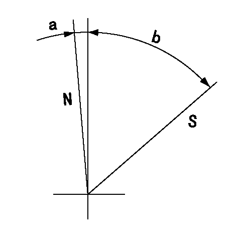
N:Pump normal
S:Stop the pump.
----------
----------
a=(0deg) b=(53deg)
----------
----------
a=(0deg) b=(53deg)
Timing setting

(1)Pump vertical direction
(2)Coupling's key groove position at No 1 cylinder's beginning of injection
(3)-
(4)-
----------
----------
a=(40deg)
----------
----------
a=(40deg)
Information:
Bolts And Bolt Torque
A bolt which is too long may "bottom" before the head is tight against the part it is to hold. The threads can be damaged when a "long" bolt is removed.If a bolt is too short, there may not be enough threads engaged to hold the part securely.Apply proper torque values to all bolts and nuts when assembling Caterpillar equipment. When a specific torque value is required, the value is listed in the SPECIFICATIONS section of the Service Manual. Tighten all other bolts and nuts for general usage, hydraulic valve bodies, or taperlock studs to the torque values given in the torque charts.T-T-T Procedure
A torque-turn-tighten (T-T-T) procedure is used in many specifications and instructions.1. Clean the bolt and nut threads.2. Put lubricant on the threads and the seat face of the bolt and the nut.3. Turn the bolt or the nut tight according to the torque specification.4. Put a location mark on the part and on the bolt or the nut.5. Turn the bolt or the nut tighter the amount of degrees according to the specifications. The side of a nut or bolt head can be used for reference if a mark can not be put on. Torque Wrench Extension
When a torque wrench extension is used with a torque wrench, the torque indication on the torque wrench will be less than the real torque.
TORQUE WRENCH WITH TORQUE WRENCH EXTENSION
E: Torque wrench drive axis-to-torque wrench extension drive axis. W: Mark on handle-to-torque wrench drive axis.1. Put a mark on the handle. Measure the handle from the mark to the axis of the torque wrench drive (W).2. Measure the torque wrench extension from the torque wrench drive to the axis of the torque wrench extension drive (E).3. To get correct torque indication (TI) when the real torque (RT) is known: Example: W = 12 in. (304.8 mm); E = 2.56 in. (65.0 mm); RT (from specifications) = 125 lb. ft. (170 N m). 4. Hold the torque wrench handle with the longest finger of the hand over the mark on the handle to get the real torque (RT) with low torque indication (TI) on the torque wrench.Locks
Flat metal locks must be installed properly to be effective. Bend one end of the lock around the edge of the part. Bend the other end against one flat surface of the nut or bolt head.Always install new locks in compartments which house moving parts.If lockwashers are installed on housings made of aluminum, use a flat washer between the lockwasher and the housing. Lines And Wires
When removing or disconnecting a group of lines or wires, tag each one to assure proper assembly.Lubrication
Where applicable, fill the compartments of the components serviced with the amount, type and grade of lubricant recommended in the Lubrication and Maintenance Guide.Rust Preventive Compound
Clean the rust preventive compound from all machined surfaces of new parts before installing them.Shims
When shims are removed, tie them together and identify them as to location. Keep shims clean and flat until they are
Have questions with 106682-4280?
Group cross 106682-4280 ZEXEL
Kubota
106682-4280
9 400 617 544
1452603210
INJECTION-PUMP ASSEMBLY
LH105CS
LH105CS