Information injection-pump assembly
BOSCH
F 019 Z20 172
f019z20172
ZEXEL
106682-3121
1066823121
HINO
220206471A
220206471a

Rating:
Service parts 106682-3121 INJECTION-PUMP ASSEMBLY:
1.
_
5.
AUTOM. ADVANCE MECHANIS
8.
_
9.
_
11.
Nozzle and Holder
12.
Open Pre:MPa(Kqf/cm2)
16.7(170)/23.5(220)
14.
NOZZLE
Include in #1:
106682-3121
as INJECTION-PUMP ASSEMBLY
Cross reference number
BOSCH
F 019 Z20 172
f019z20172
ZEXEL
106682-3121
1066823121
HINO
220206471A
220206471a
Zexel num
Bosch num
Firm num
Name
106682-3121
F 019 Z20 172
220206471A HINO
INJECTION-PUMP ASSEMBLY
K13C-TI K 14CA INJECTION PUMP ASSY PE6P,6PD PE
K13C-TI K 14CA INJECTION PUMP ASSY PE6P,6PD PE
Calibration Data:
Adjustment conditions
Test oil
1404 Test oil ISO4113 or {SAEJ967d}
1404 Test oil ISO4113 or {SAEJ967d}
Test oil temperature
degC
40
40
45
Nozzle and nozzle holder
105780-8130
Bosch type code
EFEP215A
Nozzle
105780-0050
Bosch type code
DN6TD119NP1T
Nozzle holder
105780-2090
Bosch type code
EFEP215
Opening pressure
MPa
17.2
Opening pressure
kgf/cm2
175
Injection pipe
Outer diameter - inner diameter - length (mm) mm 8-4-1000
Outer diameter - inner diameter - length (mm) mm 8-4-1000
Overflow valve
131424-9020
Overflow valve opening pressure
kPa
255
221
289
Overflow valve opening pressure
kgf/cm2
2.6
2.25
2.95
Tester oil delivery pressure
kPa
255
255
255
Tester oil delivery pressure
kgf/cm2
2.6
2.6
2.6
Direction of rotation (viewed from drive side)
Left L
Left L
Injection timing adjustment
Direction of rotation (viewed from drive side)
Left L
Left L
Injection order
1-4-2-6-
3-5
Pre-stroke
mm
3.7
3.67
3.73
Beginning of injection position
Drive side NO.1
Drive side NO.1
Difference between angles 1
Cal 1-4 deg. 60 59.75 60.25
Cal 1-4 deg. 60 59.75 60.25
Difference between angles 2
Cyl.1-2 deg. 120 119.75 120.25
Cyl.1-2 deg. 120 119.75 120.25
Difference between angles 3
Cal 1-6 deg. 180 179.75 180.25
Cal 1-6 deg. 180 179.75 180.25
Difference between angles 4
Cal 1-3 deg. 240 239.75 240.25
Cal 1-3 deg. 240 239.75 240.25
Difference between angles 5
Cal 1-5 deg. 300 299.75 300.25
Cal 1-5 deg. 300 299.75 300.25
Injection quantity adjustment
Adjusting point
A
Rack position
11.9
Pump speed
r/min
900
900
900
Average injection quantity
mm3/st.
304
301
307
Max. variation between cylinders
%
0
-3
3
Basic
*
Fixing the rack
*
Boost pressure
kPa
57.3
57.3
Boost pressure
mmHg
430
430
Injection quantity adjustment_02
Adjusting point
C
Rack position
6.4+-0.5
Pump speed
r/min
360
360
360
Average injection quantity
mm3/st.
9
6
12
Max. variation between cylinders
%
0
-15
15
Fixing the rack
*
Boost pressure
kPa
0
0
0
Boost pressure
mmHg
0
0
0
Boost compensator adjustment
Pump speed
r/min
800
800
800
Rack position
R1-2.25
Boost pressure
kPa
17.3
14.6
20
Boost pressure
mmHg
130
110
150
Boost compensator adjustment_02
Pump speed
r/min
800
800
800
Rack position
R1(12.95
)
Boost pressure
kPa
44
44
44
Boost pressure
mmHg
330
330
330
Test data Ex:
Governor adjustment
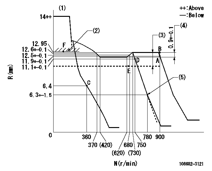
N:Pump speed
R:Rack position (mm)
(1)Notch fixed: K
(2)Boost compensator excessive fuel lever at operation: L1 (at 0 boost pressure)
(3)Boost compensator stroke: BCL
(4)Rack difference between N = N1 and N = N2
(5)Idle sub spring setting: L2.
----------
K=9 L1=13.3+-0.1mm BCL=2.25+-0.1mm N1=850r/min N2=500r/min L2=6.3-0.5mm
----------
----------
K=9 L1=13.3+-0.1mm BCL=2.25+-0.1mm N1=850r/min N2=500r/min L2=6.3-0.5mm
----------
Speed control lever angle
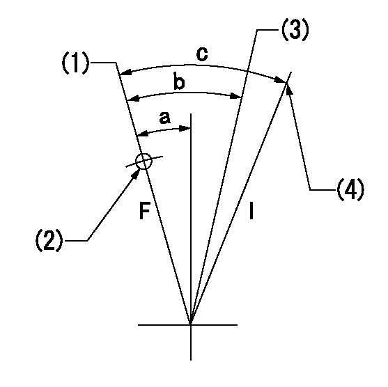
F:Full speed
I:Idle
(1)Set the pump speed at aa. ( At delivery )
(2)Use the hole at R = bb
(3)When speed is set at cc.
(4)Stopper bolt setting
----------
aa=900r/min bb=100mm cc=750r/min
----------
a=(1deg)+-5deg b=(9deg)+-5deg c=(24deg)+-5deg
----------
aa=900r/min bb=100mm cc=750r/min
----------
a=(1deg)+-5deg b=(9deg)+-5deg c=(24deg)+-5deg
Stop lever angle
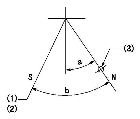
N:Pump normal
S:Stop the pump.
(1)Rack position aa or less, pump speed bb
(2)Normal stop
(3)Use the hole above R = cc
----------
aa=5.9mm bb=0r/min cc=25mm
----------
a=27deg+-5deg b=53deg+-5deg
----------
aa=5.9mm bb=0r/min cc=25mm
----------
a=27deg+-5deg b=53deg+-5deg
0000001101
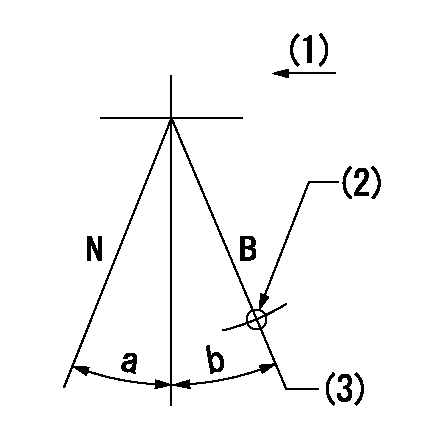
N:Normal
B:When boosted
(1)Drive side
(2)Use the hole at R = aa
(3)Rack position = bb (point F; at boost pressure = 0)
----------
aa=50mm bb=13.3+-0.1mm
----------
a=(15deg) b=(10deg)
----------
aa=50mm bb=13.3+-0.1mm
----------
a=(15deg) b=(10deg)
Timing setting

(1)Pump vertical direction
(2)Coupling's key groove position at No 1 cylinder's beginning of injection
(3)B.T.D.C.: aa
(4)-
----------
aa=16deg
----------
a=(3deg)
----------
aa=16deg
----------
a=(3deg)
Information:
Pressing Parts
When one part is pressed into another, use white lead or a suitable prepared compound to lubricate the mating surfaces.Assemble tapered parts dry. Before assembling parts with tapered splines, be sure the splines are clean, dry and free from burrs. Position the parts together by hand to mesh the splines before applying pressure.Parts which are fitted together with tapered splines are always very tight. If they are not tight, inspect the tapered splines and discard the part if the splines are worn.Bolts And Bolt Torque
Use bolts of the correct length. A bolt which is too long may "bottom" before the head is tight against the part it is to hold. The threads can be damaged when a "long" bolt is removed.If a bolt is too short, there may not be enough threads engaged to hold the part securely.Apply proper torque values to all bolts and nuts when assembling Caterpillar equipment. When a specific torque value is required, the value is listed in the SPECIFICATIONS or the DISASSEMBLY AND ASSEMBLY sections of the Service Manual. Tighten all other bolts and nuts for general usage, hydraulic valve bodies, or taperlock studs to the torque values given in the charts at the front of the SPECIFICATIONS.Locks
Lockwashers, flat metal locks or cotter pins are used to lock nuts and bolts.Flat metal locks must be installed properly to be effective. Bend one end of the lock around the edge of the part. Bend the other end against one flat surface of the nut or bolt head.Always install new locks in compartments which house moving parts.When installing lockwashers on housings made of aluminum, use a flat washer between the lockwasher and the housing.
Correct and incorrect methods of installing flat metal locks.
Correct and incorrect method for lock positioning and bending.Lines And Wires
When removing or disconnecting a group of lines or wires, tag each one to assure proper assembly.Lubrication
Where applicable, fill the compartments of the components serviced with the amount, type and grade of lubricant recommended in the Lubrication and Maintenance Information part of this Manual.Rust Preventive Compound
Clean the rust preventive compound from all machined surfaces of new parts before installing them.Shims
When shims are removed, tie them together and identify them as to location. Keep shims clean and flat until they are reinstalled.Bearings
Anti-Friction Bearings
When an anti-friction bearing is removed, cover it to keep out dirt and abrasives. Wash bearings in nonflammable cleaning solution and allow them to drain dry. The bearing may be dried with compressed air but do not spin the bearing.Discard the bearings if the races and balls or rollers are pitted, scored or burned. If the bearing is serviceable, coat it with oil and wrap it in clean paper. Do not unwrap new bearings until time of installation.The life of an anti-friction bearing will be shortened if not properly lubricated. Dirt in an anti-friction bearing can cause the bearing to lock resulting in the shaft turning in the inner race or the outer race turning within the cage.
Effect of dirt in bearing.Double
Have questions with 106682-3121?
Group cross 106682-3121 ZEXEL
Hino
106682-3121
F 019 Z20 172
220206471A
INJECTION-PUMP ASSEMBLY
K13C-TI
K13C-TI