Information injection-pump assembly
BOSCH
9 400 613 485
9400613485
ZEXEL
106682-3120
1066823120
HINO
220206470A
220206470a
Rating:
Service parts 106682-3120 INJECTION-PUMP ASSEMBLY:
1.
_
5.
AUTOM. ADVANCE MECHANIS
8.
_
9.
_
11.
Nozzle and Holder
236003620A
12.
Open Pre:MPa(Kqf/cm2)
16.7{170}/23.5{240}
14.
NOZZLE
Include in #1:
106682-3120
as INJECTION-PUMP ASSEMBLY
Cross reference number
BOSCH
9 400 613 485
9400613485
ZEXEL
106682-3120
1066823120
HINO
220206470A
220206470a
Zexel num
Bosch num
Firm num
Name
9 400 613 485
220206470A HINO
INJECTION-PUMP ASSEMBLY
K13C-TI * K 14CA PE6P,6PD PE
K13C-TI * K 14CA PE6P,6PD PE
Calibration Data:
Adjustment conditions
Test oil
1404 Test oil ISO4113 or {SAEJ967d}
1404 Test oil ISO4113 or {SAEJ967d}
Test oil temperature
degC
40
40
45
Nozzle and nozzle holder
105780-8130
Bosch type code
EFEP215A
Nozzle
105780-0050
Bosch type code
DN6TD119NP1T
Nozzle holder
105780-2090
Bosch type code
EFEP215
Opening pressure
MPa
17.2
Opening pressure
kgf/cm2
175
Injection pipe
Outer diameter - inner diameter - length (mm) mm 8-4-1000
Outer diameter - inner diameter - length (mm) mm 8-4-1000
Overflow valve
131424-9020
Overflow valve opening pressure
kPa
255
221
289
Overflow valve opening pressure
kgf/cm2
2.6
2.25
2.95
Tester oil delivery pressure
kPa
255
255
255
Tester oil delivery pressure
kgf/cm2
2.6
2.6
2.6
Direction of rotation (viewed from drive side)
Left L
Left L
Injection timing adjustment
Direction of rotation (viewed from drive side)
Left L
Left L
Injection order
1-4-2-6-
3-5
Pre-stroke
mm
3.7
3.67
3.73
Beginning of injection position
Drive side NO.1
Drive side NO.1
Difference between angles 1
Cal 1-4 deg. 60 59.75 60.25
Cal 1-4 deg. 60 59.75 60.25
Difference between angles 2
Cyl.1-2 deg. 120 119.75 120.25
Cyl.1-2 deg. 120 119.75 120.25
Difference between angles 3
Cal 1-6 deg. 180 179.75 180.25
Cal 1-6 deg. 180 179.75 180.25
Difference between angles 4
Cal 1-3 deg. 240 239.75 240.25
Cal 1-3 deg. 240 239.75 240.25
Difference between angles 5
Cal 1-5 deg. 300 299.75 300.25
Cal 1-5 deg. 300 299.75 300.25
Injection quantity adjustment
Adjusting point
A
Rack position
11.9
Pump speed
r/min
900
900
900
Average injection quantity
mm3/st.
304
301
307
Max. variation between cylinders
%
0
-3
3
Basic
*
Fixing the rack
*
Boost pressure
kPa
57.3
57.3
Boost pressure
mmHg
430
430
Injection quantity adjustment_02
Adjusting point
C
Rack position
6.4+-0.5
Pump speed
r/min
360
360
360
Average injection quantity
mm3/st.
9
6
12
Max. variation between cylinders
%
0
-15
15
Fixing the rack
*
Boost pressure
kPa
0
0
0
Boost pressure
mmHg
0
0
0
Boost compensator adjustment
Pump speed
r/min
800
800
800
Rack position
R1-2.75
Boost pressure
kPa
11.3
8.6
14
Boost pressure
mmHg
85
65
105
Boost compensator adjustment_02
Pump speed
r/min
800
800
800
Rack position
R1(12.95
)
Boost pressure
kPa
44
44
44
Boost pressure
mmHg
330
330
330
Test data Ex:
Governor adjustment
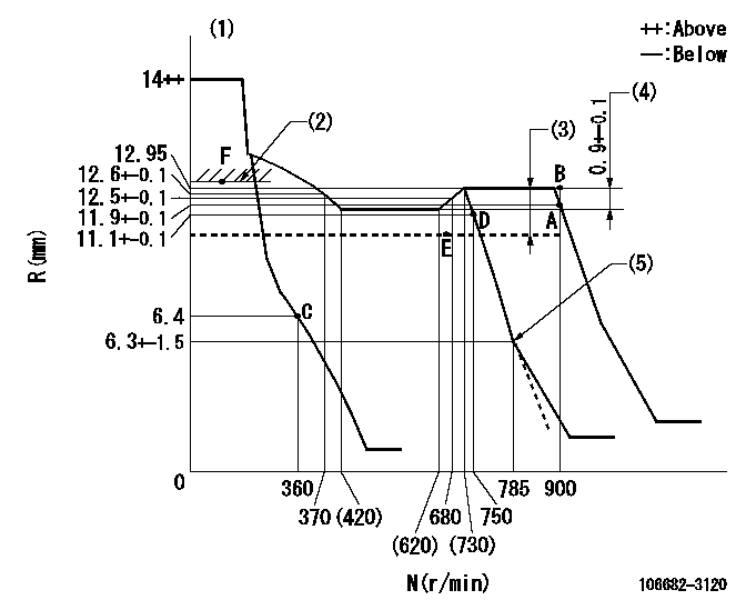
N:Pump speed
R:Rack position (mm)
(1)Notch fixed: K
(2)Boost compensator excessive fuel lever at operation (at 0 boost pressure): L1
(3)Boost compensator stroke: BCL
(4)Rack difference between N = N1 and N = N2
(5)Idle sub spring setting: L2.
----------
K=10 L1=13.3+-0.1mm BCL=2.75+-0.1mm N1=850r/min N2=500r/min L2=6.3-0.5mm
----------
----------
K=10 L1=13.3+-0.1mm BCL=2.75+-0.1mm N1=850r/min N2=500r/min L2=6.3-0.5mm
----------
Speed control lever angle
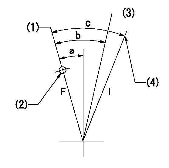
F:Full speed
I:Idle
(1)Set the pump speed at aa. ( At delivery )
(2)Use the hole at R = bb
(3)When speed is set at cc.
(4)Stopper bolt setting
----------
aa=900r/min bb=100mm cc=750r/min
----------
a=(2deg)+-5deg b=(6deg)+-5deg c=(21deg)+-5deg
----------
aa=900r/min bb=100mm cc=750r/min
----------
a=(2deg)+-5deg b=(6deg)+-5deg c=(21deg)+-5deg
Stop lever angle
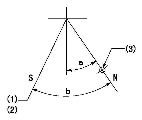
N:Pump normal
S:Stop the pump.
(1)Rack position aa or less, pump speed bb
(2)Normal stop
(3)Use the hole above R = cc
----------
aa=5.9mm bb=0r/min cc=25mm
----------
a=27deg+-5deg b=53deg+-5deg
----------
aa=5.9mm bb=0r/min cc=25mm
----------
a=27deg+-5deg b=53deg+-5deg
0000001101
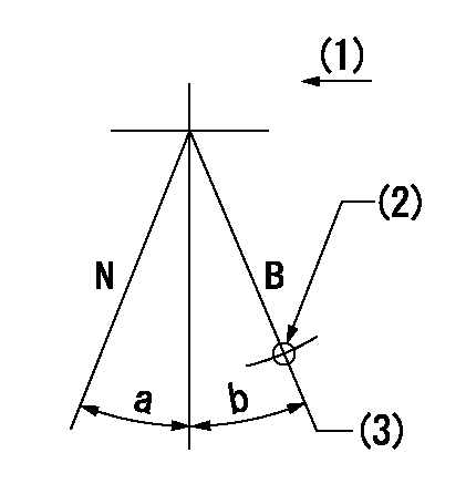
N:Normal
B:When boosted
(1)Drive side
(2)Use the hole at R = aa
(3)Rack position = bb (point F; at boost pressure = 0)
----------
aa=50mm bb=13.3+-0.1mm
----------
a=(15deg) b=(8deg)
----------
aa=50mm bb=13.3+-0.1mm
----------
a=(15deg) b=(8deg)
Timing setting

(1)Pump vertical direction
(2)Coupling's key groove position at No 1 cylinder's beginning of injection
(3)B.T.D.C.: aa
(4)-
----------
aa=16deg
----------
a=(3deg)
----------
aa=16deg
----------
a=(3deg)
Information:
Start the engine. Cover the radiator to reduce air flow and cooling. The reading on the instrument panel gauge should agree with the reading on the 2F7112 Thermometer.Radiator Filler Cap
If the pressure check indicates that the system is unable to hold pressure, the source of the pressure leak must be determined. One of the causes of cooling system pressure loss can be a faulty radiator cap seal. Inspect the radiator cap carefully for possible damage to the seal or sealing surfaces. The build-up of deposits on the cap, seal and filler neck should be removed.Water Temperature Regulator
The opening temperature of the regulator (bench test in atmospheric pressure) should be approximately 165 1°F (74 1°C). The regulator should be fully open at approximately 180°F (85°C).1. Remove the regulator from the cylinder head.2. Suspend the regulator and a thermometer in a pan of water as shown.3. Apply heat to the pan and stir the water to maintain uniformity.4. Observe the opening temperature of the regulator.If the regulator does not operate correctly, install a new regulator.
Testing water temperature regulator.Cleaning The Cooling System
It is advisable to periodically clean the cooling system. To clean the cooling system, start the engine and allow the coolant to reach operating temperature, then proceed as follows: 1. Stop the engine and drain coolant as soon as possible.2. Close drains and degrease the cooling system if grease is evident in the top tank. Fill the cooling system using two and one-half pounds of Sal Soda to every ten gallons of water.3. Start the engine and run it at operating temperature for at least ten minutes.4. Stop the engine, drain and flush the system thoroughly. Any significant amount of Sal Soda solution left in the cooling system, will decrease the effectiveness of the following cleaning procedure.5. Fill the system with a solution of one pound of Oxalic Acid or Sodium Bisulfate to every five gallons of water.6. Start the engine and run it at operating temperature for 30 to 60 minutes. Stop the engine. Drain and flush the cooling system until water is clear.7. Fill the cooling system with a solution of one-half pound of Sal Soda for every ten gallons of water, and then run the engine for ten minutes.8. Drain, flush, and fill the system with fresh water and corrosion inhibitor, or the desired amount of anti-freeze.Electrical System
Most of the electrical system testing can be performed on the vehicle. The wiring insulation must be in satisfactory condition, the wire and cable connections both clean and tight and the battery fully charged. It should be remembered an "on-vehicle" test usually indicates a component must be removed for further testing.Battery
A load test should be made on a battery that discharges very rapidly when in use. To do this apply a resistance of three times the ampere/hour rating of the battery across the battery main terminals. Allow the resistance to discharge the battery for 15 seconds and immediately test the battery voltage. A 6 volt battery in good condition will