Information injection-pump assembly
BOSCH
9 400 617 525
9400617525
ZEXEL
106682-3102
1066823102
HINO
220206152A
220206152a
Rating:
Service parts 106682-3102 INJECTION-PUMP ASSEMBLY:
1.
_
5.
AUTOM. ADVANCE MECHANIS
8.
_
9.
_
11.
Nozzle and Holder
23600-3440A
12.
Open Pre:MPa(Kqf/cm2)
17.7{180}/21.6{220}
14.
NOZZLE
Include in #1:
106682-3102
as INJECTION-PUMP ASSEMBLY
Cross reference number
BOSCH
9 400 617 525
9400617525
ZEXEL
106682-3102
1066823102
HINO
220206152A
220206152a
Zexel num
Bosch num
Firm num
Name
106682-3102
9 400 617 525
220206152A HINO
INJECTION-PUMP ASSEMBLY
P11B-TI K 14CA INJECTION PUMP ASSY PE6P,6PD PE
P11B-TI K 14CA INJECTION PUMP ASSY PE6P,6PD PE
Calibration Data:
Adjustment conditions
Test oil
1404 Test oil ISO4113 or {SAEJ967d}
1404 Test oil ISO4113 or {SAEJ967d}
Test oil temperature
degC
40
40
45
Nozzle and nozzle holder
105780-8130
Bosch type code
EFEP215A
Nozzle
105780-0050
Bosch type code
DN6TD119NP1T
Nozzle holder
105780-2090
Bosch type code
EFEP215
Opening pressure
MPa
17.2
Opening pressure
kgf/cm2
175
Injection pipe
Outer diameter - inner diameter - length (mm) mm 8-4-1000
Outer diameter - inner diameter - length (mm) mm 8-4-1000
Overflow valve
134424-0820
Overflow valve opening pressure
kPa
127
107
147
Overflow valve opening pressure
kgf/cm2
1.3
1.1
1.5
Tester oil delivery pressure
kPa
157
157
157
Tester oil delivery pressure
kgf/cm2
1.6
1.6
1.6
Direction of rotation (viewed from drive side)
Right R
Right R
Injection timing adjustment
Direction of rotation (viewed from drive side)
Right R
Right R
Injection order
1-4-2-6-
3-5
Pre-stroke
mm
3.3
3.27
3.33
Beginning of injection position
Drive side NO.1
Drive side NO.1
Difference between angles 1
Cal 1-4 deg. 60 59.75 60.25
Cal 1-4 deg. 60 59.75 60.25
Difference between angles 2
Cyl.1-2 deg. 120 119.75 120.25
Cyl.1-2 deg. 120 119.75 120.25
Difference between angles 3
Cal 1-6 deg. 180 179.75 180.25
Cal 1-6 deg. 180 179.75 180.25
Difference between angles 4
Cal 1-3 deg. 240 239.75 240.25
Cal 1-3 deg. 240 239.75 240.25
Difference between angles 5
Cal 1-5 deg. 300 299.75 300.25
Cal 1-5 deg. 300 299.75 300.25
Injection quantity adjustment
Adjusting point
A
Rack position
14.7
Pump speed
r/min
1150
1150
1150
Average injection quantity
mm3/st.
429
426
432
Max. variation between cylinders
%
0
-3
3
Basic
*
Fixing the lever
*
Boost pressure
kPa
200
200
Boost pressure
mmHg
1500
1500
Injection quantity adjustment_02
Adjusting point
C
Rack position
6.1+-0.5
Pump speed
r/min
285
285
285
Average injection quantity
mm3/st.
11
9
13
Max. variation between cylinders
%
0
-15
15
Fixing the rack
*
Boost pressure
kPa
0
0
0
Boost pressure
mmHg
0
0
0
Injection quantity adjustment_03
Adjusting point
D
Rack position
R1(10.8)
Pump speed
r/min
700
700
700
Average injection quantity
mm3/st.
191
188
194
Fixing the lever
*
Boost pressure
kPa
0
0
0
Boost pressure
mmHg
0
0
0
Boost compensator adjustment
Pump speed
r/min
700
700
700
Rack position
R1(10.8)
Boost pressure
kPa
41.3
38.6
44
Boost pressure
mmHg
310
290
330
Boost compensator adjustment_02
Pump speed
r/min
700
700
700
Rack position
R2(14.7)
Boost pressure
kPa
187
187
187
Boost pressure
mmHg
1400
1400
1400
Test data Ex:
Governor adjustment
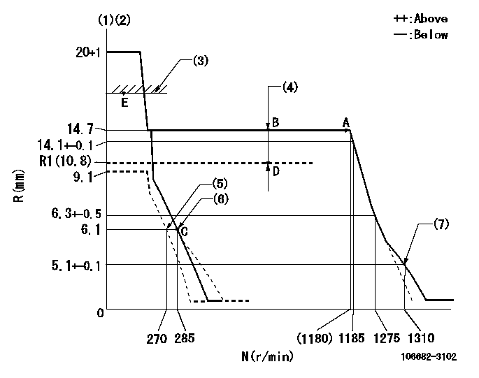
N:Pump speed
R:Rack position (mm)
(1)Target notch: K
(2)Tolerance for racks not indicated: +-0.05mm.
(3)Boost compensator excessive fuel lever at operation: L1 (at 0 boost pressure)
(4)Boost compensator stroke: BCL
(5)Set idle sub-spring
(6)Main spring setting
(7)Damper spring setting
----------
K=14 L1=16+-0.1mm BCL=(3.9)mm
----------
----------
K=14 L1=16+-0.1mm BCL=(3.9)mm
----------
Speed control lever angle

F:Full speed
I:Idle
(1)Stopper bolt setting
----------
----------
a=22deg+-5deg b=40deg+-5deg
----------
----------
a=22deg+-5deg b=40deg+-5deg
Stop lever angle
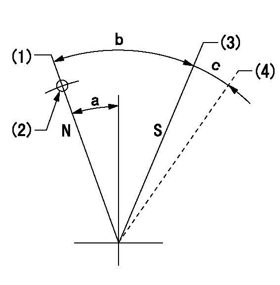
N:Pump normal
S:Stop the pump.
(1)Normal
(2)Use the hole at R = aa
(3)Contacts inner boss.
(4)Contacts outer boss.
----------
aa=23mm
----------
a=27deg+-5deg b=53deg+-5deg c=(11deg)
----------
aa=23mm
----------
a=27deg+-5deg b=53deg+-5deg c=(11deg)
0000001101
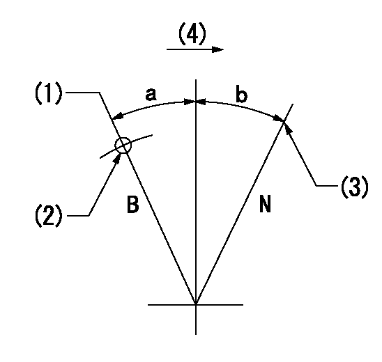
N:Normal
B:When boosted
(1)Rack position = aa at boost pressure 0.
(2)Use the hole at R = bb
(3)Stopper bolt setting
(4)Drive side
----------
aa=16+-0.1mm bb=30mm
----------
a=(20deg) b=(15deg)
----------
aa=16+-0.1mm bb=30mm
----------
a=(20deg) b=(15deg)
0000001501 Q ADJUSTMENT PIPING
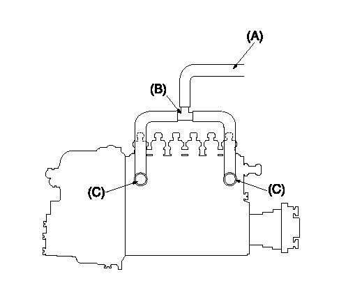
Tester fuel pipe A
(B) branch piping
Fuel inlet C
Piping at standard injection quantity adjustment
1. Because the pump gallery is divided into two, be careful of the fuel piping at adjustment.
----------
----------
----------
----------
Timing setting

(1)Pump vertical direction
(2)Coupling's key groove position at No 1 cylinder's beginning of injection
(3)B.T.D.C.: aa
(4)-
----------
aa=20deg
----------
a=(50deg)
----------
aa=20deg
----------
a=(50deg)
Information:
Introduction
The following Special Instruction must be used to package a DPF for a core return.
Wear goggles, gloves, protective clothing, and a National Institute for Occupational Safety and Health (NIOSH) approved P95 or N95 half-face respirator when handling a used Diesel Particulate Filter or Catalytic Converter Muffler. Failure to do so could result in personal injury.
Note: Whenever the filter is replaced the engine ash model must be reset. Refer to the section below for information on how to reset the ash model.Reset the Engine Ash Model
The engine ash model must be reset whenever the filter is cleaned or replaced. Reseting the ash model places the DPF volume back to the "Clean State". The resetting will allow the regeneration of the DPF to function properly.
Connect to Cat® Electronic Technician (Cat® ET).
Illustration 1 g03345441
Connect to "Engine #1 Aftertreatment Controller".
Illustration 2 g03345627
Select "Service" from the top menu and select "Service Procedures".
Illustration 3 g03345631
From the "Service Procedures" menu, select "DPF Ash Service".
Select "Start".
Illustration 4 g03345633
Select "Ash Service Reset" to start the reset procedure.
Illustration 5 g03345638
You must read the warning and select "Agree" in order to continue.
Illustration 6 g03345643
Choose the correct replacement type of DPF in the menu that appears. The types of replacements for the DPF are the following:
"Field Cleaned" A DPF that has been cleaned and reapplied.
"New" A new DPF replacement
"Remanufactured" A remanufactured DPF replacement.
Illustration 7 g03345648
Illustration 8 g03345650
One the reset is completed, a log of the reset is captured and visible as a new row of information in the DPF Ash Service screen. Resetting the engine ash model does not reset the soot level.
Perform a "Manual DPF Regeneration" with Cat® ET to reset the soot level.Packaging Instructions
Note: The replacement DPF will be packaged with a bag and zip-tie that are used to repackage the DPF that has been removed.
Place the DPF being returned in the enclosed bag and seal the bag with the enclosed zip-tie.
Place the enclosed warning label on the outside of the bag.
Place half of the foam insert on the bottom of the original shipping box with the cut out in the insert facing up.
Place the DPF into the box fitting the DPF into the cut out in the insert.
Place the second half of the foam insert on to of the DPF with the cut out in the insert facing down onto the DPF.
Seal the box with packing tape.Note: If the package weighs over 16 kg (35 lb), additional tape or banding might be required.
Label the package for return shipment.
Have questions with 106682-3102?
Group cross 106682-3102 ZEXEL
Hino
106682-3102
9 400 617 525
220206152A
INJECTION-PUMP ASSEMBLY
P11B-TI
P11B-TI