Information injection-pump assembly
ZEXEL
106682-3101
1066823101
HINO
220206151A
220206151a
Rating:
Cross reference number
ZEXEL
106682-3101
1066823101
HINO
220206151A
220206151a
Zexel num
Bosch num
Firm num
Name
Calibration Data:
Adjustment conditions
Test oil
1404 Test oil ISO4113 or {SAEJ967d}
1404 Test oil ISO4113 or {SAEJ967d}
Test oil temperature
degC
40
40
45
Nozzle and nozzle holder
105780-8130
Bosch type code
EFEP215A
Nozzle
105780-0050
Bosch type code
DN6TD119NP1T
Nozzle holder
105780-2090
Bosch type code
EFEP215
Opening pressure
MPa
17.2
Opening pressure
kgf/cm2
175
Injection pipe
Outer diameter - inner diameter - length (mm) mm 8-4-1000
Outer diameter - inner diameter - length (mm) mm 8-4-1000
Overflow valve
134424-0820
Overflow valve opening pressure
kPa
127
127
127
Overflow valve opening pressure
kgf/cm2
1.3
1.3
1.3
Tester oil delivery pressure
kPa
157
157
157
Tester oil delivery pressure
kgf/cm2
1.6
1.6
1.6
Direction of rotation (viewed from drive side)
Right R
Right R
Injection timing adjustment
Direction of rotation (viewed from drive side)
Right R
Right R
Injection order
1-4-2-6-
3-5
Pre-stroke
mm
3.3
3.27
3.33
Beginning of injection position
Drive side NO.1
Drive side NO.1
Difference between angles 1
Cal 1-4 deg. 60 59.75 60.25
Cal 1-4 deg. 60 59.75 60.25
Difference between angles 2
Cyl.1-2 deg. 120 119.75 120.25
Cyl.1-2 deg. 120 119.75 120.25
Difference between angles 3
Cal 1-6 deg. 180 179.75 180.25
Cal 1-6 deg. 180 179.75 180.25
Difference between angles 4
Cal 1-3 deg. 240 239.75 240.25
Cal 1-3 deg. 240 239.75 240.25
Difference between angles 5
Cal 1-5 deg. 300 299.75 300.25
Cal 1-5 deg. 300 299.75 300.25
Injection quantity adjustment
Adjusting point
A
Rack position
15
Pump speed
r/min
1150
1150
1150
Average injection quantity
mm3/st.
447
444
450
Max. variation between cylinders
%
0
-3
3
Basic
*
Fixing the lever
*
Boost pressure
kPa
200
200
Boost pressure
mmHg
1500
1500
Injection quantity adjustment_02
Adjusting point
C
Rack position
6.1+-0.5
Pump speed
r/min
285
285
285
Average injection quantity
mm3/st.
11
9
13
Max. variation between cylinders
%
0
-15
15
Fixing the rack
*
Boost pressure
kPa
0
0
0
Boost pressure
mmHg
0
0
0
Injection quantity adjustment_03
Adjusting point
D
Rack position
R1(10.8)
Pump speed
r/min
700
700
700
Average injection quantity
mm3/st.
191
188
194
Fixing the lever
*
Boost pressure
kPa
0
0
0
Boost pressure
mmHg
0
0
0
Boost compensator adjustment
Pump speed
r/min
700
700
700
Rack position
R1(10.8)
Boost pressure
kPa
41.3
38.6
44
Boost pressure
mmHg
310
290
330
Boost compensator adjustment_02
Pump speed
r/min
700
700
700
Rack position
R2(15)
Boost pressure
kPa
187
187
187
Boost pressure
mmHg
1400
1400
1400
Test data Ex:
Governor adjustment
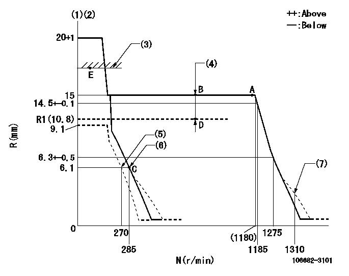
N:Pump speed
R:Rack position (mm)
(1)Target notch: K
(2)Tolerance for racks not indicated: +-0.05mm.
(3)Boost compensator excessive fuel lever at operation: L1 (at 0 boost pressure)
(4)Boost compensator stroke: BCL
(5)Set idle sub-spring
(6)Main spring setting
(7)Damper spring setting
----------
K=11 L1=16+-0.1mm BCL=(4.2)mm
----------
----------
K=11 L1=16+-0.1mm BCL=(4.2)mm
----------
Speed control lever angle

F:Full speed
I:Idle
(1)Stopper bolt setting
----------
----------
a=22deg+-5deg b=42deg+-5deg
----------
----------
a=22deg+-5deg b=42deg+-5deg
Stop lever angle
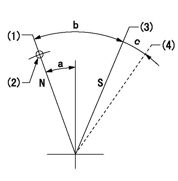
N:Pump normal
S:Stop the pump.
(1)Normal
(2)Use the hole at R = aa
(3)Inner stopper contact position
(4)Outer stopper contact position.
----------
aa=23mm
----------
a=27deg+-5deg b=53deg+-5deg c=(11deg)
----------
aa=23mm
----------
a=27deg+-5deg b=53deg+-5deg c=(11deg)
0000001101
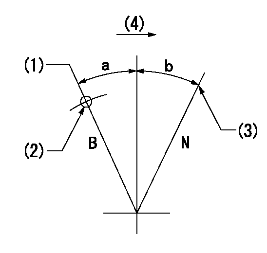
N:Normal
B:When boosted
(1)Rack position = aa at boost pressure 0.
(2)Use the hole at R = bb
(3)Stopper bolt setting
(4)Drive side
----------
aa=16+-0.1mm bb=30mm
----------
a=(20deg) b=(15deg)
----------
aa=16+-0.1mm bb=30mm
----------
a=(20deg) b=(15deg)
Timing setting

(1)Pump vertical direction
(2)Coupling's key groove position at No 1 cylinder's beginning of injection
(3)B.T.D.C.: aa
(4)-
----------
aa=20deg
----------
a=(50deg)
----------
aa=20deg
----------
a=(50deg)
Information:
1. Remove suction bell (3) and tubes, oil supply tube (2) and BrakeSaver oil supply tube (1) from the engine block and oil pump. 2. Remove three bolts (5) and oil pump (4) from the engine. The following steps are for installation of the oil pump.3. Put oil pump (4) in position on the engine. Make sure the oil pump gear is engaged with the crankshaft gear and install three bolts (5) that hold the oil pump.4. Put clean oil on the O-ring seals on the oil tubes.5. Install suction bell (3) and tubes, oil supply tube (2) and BrakeSaver oil supply tube (1).end by:a) install oil pan (BrakeSaver)Disassemble Oil Pump (Brakesaver)
start by:a) remove oil pump (BrakeSaver) 1. Remove the bolt and washer that hold drive gear (1) on the shaft.2. Use tooling (A) to remove drive gear (1) from the shaft. Remove the key from the shaft. Put marks on the pump bodies so they can be assembled in the correct position. 3. Remove retainer (3) for the bypass valve. Remove the spring and bypass valve.4. Remove bolts (4) that hold pump body (2) to the main pump body. Remove pump body (2).5. Use tooling (B) to remove the bearings from pump body (2). 6. Remove gears (7). Put marks on the gears so they can be assembled in the same position.7. Remove spacer (6) from main oil pump body (5). Use tooling (B) to remove the bearings from spacer (6).8. Remove the gears from main oil pump body (5). 9. Use tooling (B) to remove the bearings from the main oil pump body.Assemble Oil Pump (Brakesaver)
1. Use tooling (A) to install bearings (2) until they are even with the outside surface of main oil pump body (1). Install bearings (2) so the junctions in the bearings are 30° 15° from the center line of the bearing bores and toward the oil pump outlet passage as shown. 2. Use tooling (A) to install bearings (3) in the spacer. Install the bearings until they are in position an equal distance in from each side of the spacer. Install the bearings with the oil holes in the bearings in alignment with the oil holes in the spacer and the junctions in the bearings in alignment with the cavity in the spacer as shown. 3. Put clean engine oil on all the gears and bearings before they are assembled in the oil pump. Install idler and drive gears (5) in the main oil pump body.4. Install spacer (4) on the gear shafts with the smaller cavity out and the oil holes in the spacer toward the pump outlet passage as shown. 5. Use tooling (A) to install bearings (6) in pump body (7) until they are .060 .010 in. (1.52 0.25 mm) from the inside edge of the bearing bores. Install the bearings so the junctions in the bearings are 30° 15° from the center line of the bearing bores and toward the outlet passage. The