Information injection-pump assembly
BOSCH
F 01G 09U 0JC
f01g09u0jc
ZEXEL
106682-1121
1066821121
ISUZU
1156035141
1156035141
Rating:
Service parts 106682-1121 INJECTION-PUMP ASSEMBLY:
1.
_
5.
AUTOM. ADVANCE MECHANIS
7.
COUPLING PLATE
8.
_
9.
_
11.
Nozzle and Holder
12.
Open Pre:MPa(Kqf/cm2)
22.1(225)
15.
NOZZLE SET
Include in #1:
106682-1121
as INJECTION-PUMP ASSEMBLY
Cross reference number
BOSCH
F 01G 09U 0JC
f01g09u0jc
ZEXEL
106682-1121
1066821121
ISUZU
1156035141
1156035141
Zexel num
Bosch num
Firm num
Name
Calibration Data:
Adjustment conditions
Test oil
1404 Test oil ISO4113 or {SAEJ967d}
1404 Test oil ISO4113 or {SAEJ967d}
Test oil temperature
degC
40
40
45
Nozzle and nozzle holder
105780-8130
Bosch type code
EFEP215A
Nozzle
105780-0050
Bosch type code
DN6TD119NP1T
Nozzle holder
105780-2090
Bosch type code
EFEP215
Opening pressure
MPa
17.2
Opening pressure
kgf/cm2
175
Injection pipe
Outer diameter - inner diameter - length (mm) mm 8-4-1000
Outer diameter - inner diameter - length (mm) mm 8-4-1000
Overflow valve
134424-4320
Overflow valve opening pressure
kPa
255
221
289
Overflow valve opening pressure
kgf/cm2
2.6
2.25
2.95
Tester oil delivery pressure
kPa
255
255
255
Tester oil delivery pressure
kgf/cm2
2.6
2.6
2.6
Direction of rotation (viewed from drive side)
Right R
Right R
Injection timing adjustment
Direction of rotation (viewed from drive side)
Right R
Right R
Injection order
1-5-3-6-
2-4
Pre-stroke
mm
2.8
2.75
2.85
Beginning of injection position
Drive side NO.1
Drive side NO.1
Difference between angles 1
Cal 1-5 deg. 60 59.5 60.5
Cal 1-5 deg. 60 59.5 60.5
Difference between angles 2
Cal 1-3 deg. 120 119.5 120.5
Cal 1-3 deg. 120 119.5 120.5
Difference between angles 3
Cal 1-6 deg. 180 179.5 180.5
Cal 1-6 deg. 180 179.5 180.5
Difference between angles 4
Cyl.1-2 deg. 240 239.5 240.5
Cyl.1-2 deg. 240 239.5 240.5
Difference between angles 5
Cal 1-4 deg. 300 299.5 300.5
Cal 1-4 deg. 300 299.5 300.5
Injection quantity adjustment
Adjusting point
A
Rack position
11.3
Pump speed
r/min
1115
1115
1115
Average injection quantity
mm3/st.
417
413
421
Max. variation between cylinders
%
0
-3
3
Basic
*
Fixing the lever
*
Boost pressure
kPa
169
169
Boost pressure
mmHg
1270
1270
Injection quantity adjustment_02
Adjusting point
B
Rack position
4.4+-0.5
Pump speed
r/min
290
290
290
Average injection quantity
mm3/st.
18
14.8
21.2
Max. variation between cylinders
%
0
-15
15
Fixing the rack
*
Boost pressure
kPa
0
0
0
Boost pressure
mmHg
0
0
0
Boost compensator adjustment
Pump speed
r/min
550
550
550
Rack position
R1-4
Boost pressure
kPa
70
66
74
Boost pressure
mmHg
525
495
555
Boost compensator adjustment_02
Pump speed
r/min
550
550
550
Rack position
R1(11.3)
Boost pressure
kPa
156
149.3
162.7
Boost pressure
mmHg
1170
1120
1220
Test data Ex:
Governor adjustment
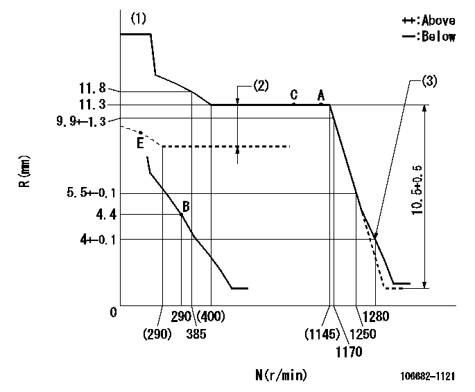
N:Pump speed
R:Rack position (mm)
(1)Tolerance for racks not indicated: +-0.05mm.
(2)Boost compensator stroke: BCL
(3)Set idle sub-spring
----------
BCL=4+-0.1mm
----------
----------
BCL=4+-0.1mm
----------
Speed control lever angle
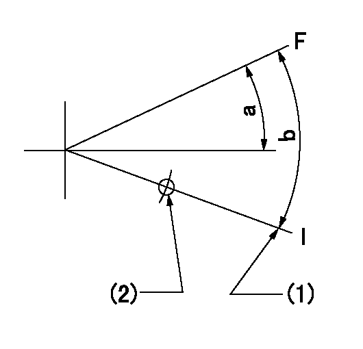
F:Full speed
I:Idle
(1)Stopper bolt setting
(2)Use the hole at R = aa
----------
aa=135mm
----------
a=(4deg)+-5deg b=(14deg)+-5deg
----------
aa=135mm
----------
a=(4deg)+-5deg b=(14deg)+-5deg
0000000901
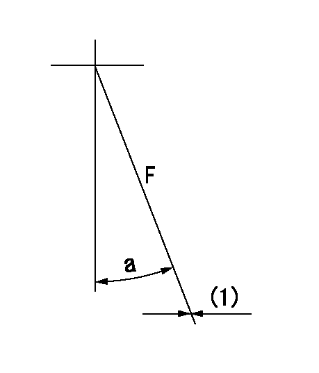
F:Full load
(1)Fix using the stopper bolt.
----------
----------
a=15deg+-5deg
----------
----------
a=15deg+-5deg
Stop lever angle
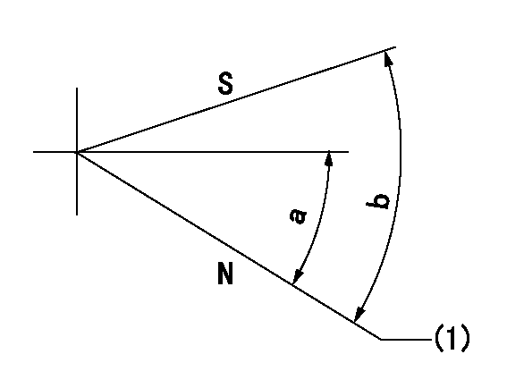
N:Pump normal
S:Stop the pump.
(1)Normal
----------
----------
a=27deg+-5deg b=71deg+-5deg
----------
----------
a=27deg+-5deg b=71deg+-5deg
0000001501 TAMPER PROOF
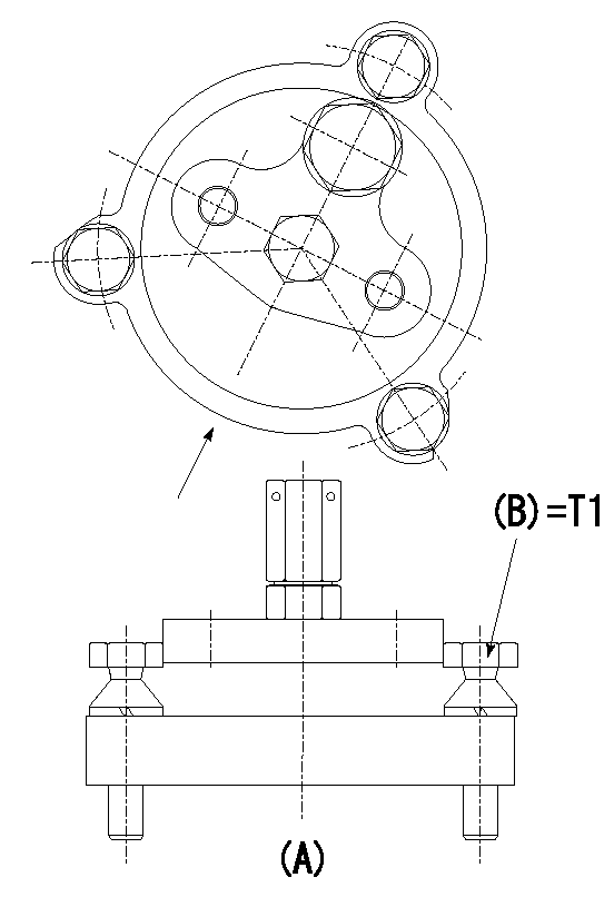
Tamperproofing-equipped boost compensator cover installation procedure
(A): figure shown by arrow
(1)Before adjusting the governor and the boost compensator, temporarily tighten the screw to the specified torque. (Do not damage the thread.)
(Tightening torque T = T1 maximum)
----------
T1=2.5N-m(0.25kgf-m)
----------
----------
T1=2.5N-m(0.25kgf-m)
----------
Timing setting

(1)Pump vertical direction
(2)Position of coupling's threaded hole at No 1 cylinder's beginning of injection
(3)B.T.D.C.: aa
(4)-
----------
aa=15deg
----------
a=(30deg)
----------
aa=15deg
----------
a=(30deg)
Information:
43. Install inner fuel injection lines (27). Use tool (H) and (J) and tighten the fuel injection line nuts to a torque of 30 5 lb. ft. (40 7 N m). 44. Make sure seals (28) are in position on the valve cover bases. Put valve cover bases (29) in position on the cylinder head. 45. Install bolts (32) that hold the valve cover bases in place. Tighten the bolts to a torque of 120 24 lb.in. (13.6 2.8 N m).46. Make sure seals (30) are in position on the valve covers. Put valve covers (31) in position on the valve cover bases. Install bolts (33) that hold the valve covers in place. Tighten the bolts to a torque of 120 24 lb.in. (13.6 2.8 N m).47. If the fan drive group was not removed, install bolts (34) that hold the bracket on the head to the timing gear cover. 48. Put breather (35) and breather tube (36) in position on the valve cover. Install the three clamps that hold them in place.49. Connect hose (37) to the cylinder head. 50. Connect air compressor water line (38) to the air compressor. 51. Connect outer fuel injection lines (39). Tighten the nuts to a torque of 30 5 lb.ft. (40 7 N m). 52. Install water temperature sensing units (42) and (43). Connect wires (40) and (41) to the water temperature sensing units. Install turbocharger tube (47), elbow (45) and inlet manifold (44) as a unit.53. Put the inlet manifold gaskets in place on the cylinder head. Put SAE 30W oil on O-ring seals (46). Slide turbocharger tube (47) into the turbocharger. Put 9S3263 Thread Lock on the threads of the bolts and install the twelve bolts that hold the inlet manifold to the cylinder head. 54. Connect oil line (48) for the fuel ratio control to the inlet manifold.55. Connect fuel lines (49), (50) and (51) to the fuel block. 56. Connect fuel line (52) to the fuel filter base. 57. Make sure the gasket is in place and put priming pump (55) in position. Install bolts (54).58. Install brackets (53) on the inlet manifold. 59. Put the gasket in place and install two bolts (57) that hold the oil drain tube to the turbocharger.60. Put the gasket in position for the oil supply tube. Install oil supply tube (56).61. If the fan drive group was removed, install the fan drive. See DISASSEMBLY AND ASSEMBLY section. 62. Put air conditioning compressor (58) in position on bracket (59). Install the four bolts that hold the compressor to the bracket. 63. Put gasket (60) in position. Install water temperature regulator (61) in the water temperature regulator housing. Install the water temperature regulator housing (62) on the cylinder head. 64. Connect the water vent line to the head. Put upper radiator hose (63) in position on the water temperature regulator housing and the radiator. Tighten the clamps that hold the upper radiator hose