Information injection-pump assembly
BOSCH
9 400 613 390
9400613390
ZEXEL
106682-1100
1066821100
ISUZU
1156034920
1156034920
Rating:
Service parts 106682-1100 INJECTION-PUMP ASSEMBLY:
1.
_
5.
AUTOM. ADVANCE MECHANIS
7.
COUPLING PLATE
8.
_
11.
Nozzle and Holder
12.
Open Pre:MPa(Kqf/cm2)
22.1{225}
15.
NOZZLE SET
Include in #1:
106682-1100
as INJECTION-PUMP ASSEMBLY
Cross reference number
BOSCH
9 400 613 390
9400613390
ZEXEL
106682-1100
1066821100
ISUZU
1156034920
1156034920
Zexel num
Bosch num
Firm num
Name
106682-1100
9 400 613 390
1156034920 ISUZU
INJECTION-PUMP ASSEMBLY
6SD1-MTC K 14CA INJECTION PUMP ASSY PE6P,6PD PE
6SD1-MTC K 14CA INJECTION PUMP ASSY PE6P,6PD PE
Calibration Data:
Adjustment conditions
Test oil
1404 Test oil ISO4113 or {SAEJ967d}
1404 Test oil ISO4113 or {SAEJ967d}
Test oil temperature
degC
40
40
45
Nozzle and nozzle holder
105780-8250
Bosch type code
1 688 901 101
Nozzle
105780-0120
Bosch type code
1 688 901 990
Nozzle holder
105780-2190
Opening pressure
MPa
20.7
Opening pressure
kgf/cm2
211
Injection pipe
Outer diameter - inner diameter - length (mm) mm 8-3-600
Outer diameter - inner diameter - length (mm) mm 8-3-600
Overflow valve
134424-1920
Overflow valve opening pressure
kPa
127
107
147
Overflow valve opening pressure
kgf/cm2
1.3
1.1
1.5
Tester oil delivery pressure
kPa
255
255
255
Tester oil delivery pressure
kgf/cm2
2.6
2.6
2.6
Direction of rotation (viewed from drive side)
Left L
Left L
Injection timing adjustment
Direction of rotation (viewed from drive side)
Left L
Left L
Injection order
1-5-3-6-
2-4
Pre-stroke
mm
3.2
3.17
3.23
Beginning of injection position
Governor side NO.1
Governor side NO.1
Difference between angles 1
Cal 1-5 deg. 60 59.75 60.25
Cal 1-5 deg. 60 59.75 60.25
Difference between angles 2
Cal 1-3 deg. 120 119.75 120.25
Cal 1-3 deg. 120 119.75 120.25
Difference between angles 3
Cal 1-6 deg. 180 179.75 180.25
Cal 1-6 deg. 180 179.75 180.25
Difference between angles 4
Cyl.1-2 deg. 240 239.75 240.25
Cyl.1-2 deg. 240 239.75 240.25
Difference between angles 5
Cal 1-4 deg. 300 299.75 300.25
Cal 1-4 deg. 300 299.75 300.25
Injection quantity adjustment
Adjusting point
A
Rack position
12.2
Pump speed
r/min
1200
1200
1200
Average injection quantity
mm3/st.
173.5
171.5
175.5
Max. variation between cylinders
%
0
-2.5
2.5
Basic
*
Fixing the lever
*
Boost pressure
kPa
189
189
Boost pressure
mmHg
1420
1420
Injection quantity adjustment_02
Adjusting point
Z
Rack position
5.4+-0.5
Pump speed
r/min
410
410
410
Average injection quantity
mm3/st.
20.5
18.5
22.5
Max. variation between cylinders
%
0
-14
14
Fixing the rack
*
Boost pressure
kPa
0
0
0
Boost pressure
mmHg
0
0
0
Boost compensator adjustment
Pump speed
r/min
600
600
600
Rack position
8.05
Boost pressure
kPa
30.7
26.7
34.7
Boost pressure
mmHg
230
200
260
Boost compensator adjustment_02
Pump speed
r/min
600
600
600
Rack position
(12.2)
Boost pressure
kPa
176
169.3
182.7
Boost pressure
mmHg
1320
1270
1370
Test data Ex:
Governor adjustment
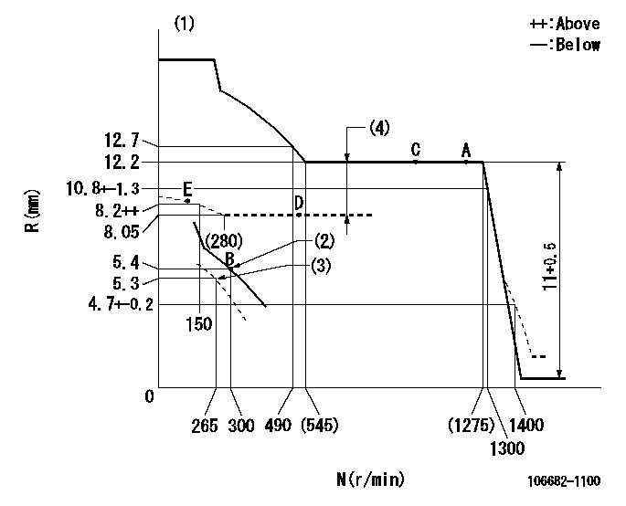
N:Pump speed
R:Rack position (mm)
(1)Tolerance for racks not indicated: +-0.05mm.
(2)Main spring setting
(3)Set idle sub-spring (with the lever free).
(4)Boost compensator stroke: BCL
----------
BCL=(4.15)mm
----------
----------
BCL=(4.15)mm
----------
Speed control lever angle
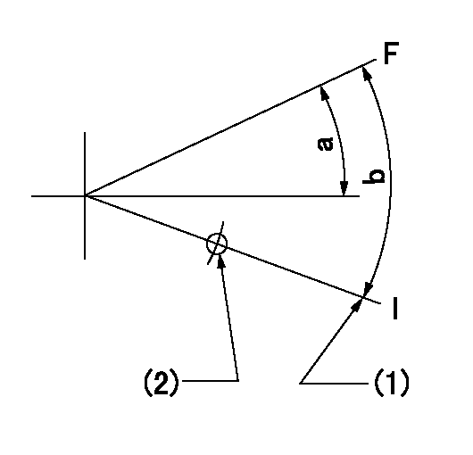
F:Full speed
I:Idle
(1)Stopper bolt setting
(2)Use the hole at R = aa
----------
aa=135mm
----------
a=6deg+-5deg b=19deg+-5deg
----------
aa=135mm
----------
a=6deg+-5deg b=19deg+-5deg
0000000901
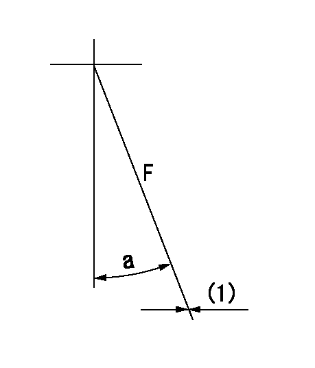
F:Full load
(1)Fix using the stopper bolt.
----------
----------
a=15deg+-5deg
----------
----------
a=15deg+-5deg
Stop lever angle

N:Pump normal
S:Stop the pump.
(1)Normal
----------
----------
a=28deg+-5deg b=71deg+-5deg
----------
----------
a=28deg+-5deg b=71deg+-5deg
Timing setting

(1)Pump vertical direction
(2)Position of coupling's threaded hole at No 1 cylinder's beginning of injection
(3)B.T.D.C.: aa
(4)-
----------
aa=19deg
----------
a=(9deg)
----------
aa=19deg
----------
a=(9deg)
Information:
Recommended Procedure
A. Outside Leaks
1. Leaks in Hoses or Connections ... Check all hoses and connections for visual signs of leakage. If no leaks are seen, look for damage to hoses or loose clamps.2. Leaks in the Radiator and/or Expansion Tank ... Put pressure to the radiator and/or expansion tank with the 9S8140 Cooling System Pressurizing Pump Group and check for leaks.3. Leaks in the Heater ... Put pressure to the cooling system with the 9S8140 Cooling System Pressurizing Pump Group and check the heater for leaks.4. Leaks in the Water Pump ... Check the water pump for leaks before starting the engine, then start the engine and look for leaks. If there are leaks at the water pump, repair or install a new water pump.5. Cylinder Head Gasket Leakage ... Look for leaks along the surface of the cylinder head gasket. If you see leaks, install a new head gasket.B. Coolant Leaks At The Overflow Tube
6. Bad Pressure Cap or Relief Valve ... Check the sealing surfaces of the pressure cap and the radiator to be sure the cap is sealing correctly. Check the opening pressure and sealing ability of the pressure cap or relief valve with the 9S8140 Cooling System Pressurizing Pump Group.7. Engine Runs Too Hot ... If coolant temperature is too high, pressure will be high enough to move the cap off of the sealing surface in the radiator and cause coolant loss through the overflow tube. See "Above Normal Heating" in COOLING SYSTEM Chart.8. Expansion Tank Too Small or Installed Wrong ... The expansion tank can be either a part of the radiator or it can be installed separately from the radiator. The expansion tank must be large enough to hold the expansion of the coolant as it gets warm or has sudden changes in pressure. Make sure the expansion tank is installed correctly, and the size is according to the recommendations of the Truck Manufacturer.9. Cylinder Head Gasket Leakage or Crack(s) in Cylinder Head or Cylinder Block...Remove the radiator cap and, with the engine running, look for air bubbles in the coolant. Bubbles in the coolant are a sign of probable leakage at the head gasket. Remove the cylinder head from the engine. Check cylinder head, cylinder walls and head gasket surface of the cylinder block for cracks. When the head is installed, use a new head gasket, spacer plate gasket, water seals, and O-ring seals.C. Inside Leakage
10. Cylinder Head Gasket Leakage ... If the cylinder head gasket leaks between a water passage and an opening into the crankcase, coolant will get into the crankcase.11. Crack(s) in Cylinder Head ... Crack(s) in the upper surface of the cylinder head, or an area between a water passage and an opening into the crankcase, can allow coolant to get into the crankcase.12. Crack(s) in Cylinder Block ... Crack(s) in the cylinder block between a water passage and the crankcase will let coolant get into the crankcase.
Have questions with 106682-1100?
Group cross 106682-1100 ZEXEL
Isuzu
106682-1100
9 400 613 390
1156034920
INJECTION-PUMP ASSEMBLY
6SD1-MTC
6SD1-MTC