Information injection-pump assembly
BOSCH
9 400 610 968
9400610968
ZEXEL
106682-1000
1066821000
ISUZU
1156031650
1156031650
Rating:
Compare Prices: .
As an associate, we earn commssions on qualifying purchases through the links below
07 Jul 2021
1.06682.1000 - Size : 1 kg - Sodium Ammonium Hydrogen Phosphate tetrahydrate, EMSURE for Analysis - Case of 6 (1kg)
MilliporeSigma Size : 1 kg || Packaging : Plastic Bottle || Supplier No. : 1.06682.1000
MilliporeSigma Size : 1 kg || Packaging : Plastic Bottle || Supplier No. : 1.06682.1000
Service parts 106682-1000 INJECTION-PUMP ASSEMBLY:
1.
_
5.
AUTOM. ADVANCE MECHANIS
7.
COUPLING PLATE
8.
_
11.
Nozzle and Holder
1-15300-361-0
12.
Open Pre:MPa(Kqf/cm2)
22.1{225}
15.
NOZZLE SET
Include in #1:
106682-1000
as INJECTION-PUMP ASSEMBLY
Cross reference number
BOSCH
9 400 610 968
9400610968
ZEXEL
106682-1000
1066821000
ISUZU
1156031650
1156031650
Zexel num
Bosch num
Firm num
Name
Calibration Data:
Adjustment conditions
Test oil
1404 Test oil ISO4113 or {SAEJ967d}
1404 Test oil ISO4113 or {SAEJ967d}
Test oil temperature
degC
40
40
45
Nozzle and nozzle holder
105780-8250
Bosch type code
1 688 901 101
Nozzle
105780-0120
Bosch type code
1 688 901 990
Nozzle holder
105780-2190
Opening pressure
MPa
20.7
Opening pressure
kgf/cm2
211
Injection pipe
Outer diameter - inner diameter - length (mm) mm 8-3-600
Outer diameter - inner diameter - length (mm) mm 8-3-600
Overflow valve
134424-1920
Overflow valve opening pressure
kPa
127
107
147
Overflow valve opening pressure
kgf/cm2
1.3
1.1
1.5
Tester oil delivery pressure
kPa
255
255
255
Tester oil delivery pressure
kgf/cm2
2.6
2.6
2.6
Direction of rotation (viewed from drive side)
Left L
Left L
Injection timing adjustment
Direction of rotation (viewed from drive side)
Left L
Left L
Injection order
1-5-3-6-
2-4
Pre-stroke
mm
3.2
3.17
3.23
Beginning of injection position
Governor side NO.1
Governor side NO.1
Difference between angles 1
Cal 1-5 deg. 60 59.75 60.25
Cal 1-5 deg. 60 59.75 60.25
Difference between angles 2
Cal 1-3 deg. 120 119.75 120.25
Cal 1-3 deg. 120 119.75 120.25
Difference between angles 3
Cal 1-6 deg. 180 179.75 180.25
Cal 1-6 deg. 180 179.75 180.25
Difference between angles 4
Cyl.1-2 deg. 240 239.75 240.25
Cyl.1-2 deg. 240 239.75 240.25
Difference between angles 5
Cal 1-4 deg. 300 299.75 300.25
Cal 1-4 deg. 300 299.75 300.25
Injection quantity adjustment
Adjusting point
A
Rack position
11.3
Pump speed
r/min
1200
1200
1200
Average injection quantity
mm3/st.
143
141
145
Max. variation between cylinders
%
0
-2.5
2.5
Basic
*
Fixing the lever
*
Boost pressure
kPa
117
117
Boost pressure
mmHg
880
880
Injection quantity adjustment_02
Adjusting point
Z
Rack position
6.6+-0.5
Pump speed
r/min
330
330
330
Average injection quantity
mm3/st.
14
12
16
Max. variation between cylinders
%
0
-14
14
Fixing the rack
*
Boost pressure
kPa
0
0
0
Boost pressure
mmHg
0
0
0
Injection quantity adjustment_03
Adjusting point
D
Rack position
-
Pump speed
r/min
100
100
100
Average injection quantity
mm3/st.
130
130
170
Fixing the lever
*
Boost pressure
kPa
0
0
0
Boost pressure
mmHg
0
0
0
Boost compensator adjustment
Pump speed
r/min
650
650
650
Rack position
8.25
Boost pressure
kPa
45.3
42.6
48
Boost pressure
mmHg
340
320
360
Boost compensator adjustment_02
Pump speed
r/min
650
650
650
Rack position
(11.3)
Boost pressure
kPa
104
97.3
110.7
Boost pressure
mmHg
780
730
830
Test data Ex:
Governor adjustment
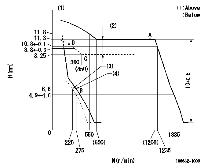
N:Pump speed
R:Rack position (mm)
(1)Tolerance for racks not indicated: +-0.05mm.
(2)Boost compensator stroke: BCL
(3)Set idle sub-spring (with the lever free).
(4)Main spring setting
----------
BCL=(3.05)+-0.1mm
----------
----------
BCL=(3.05)+-0.1mm
----------
Speed control lever angle
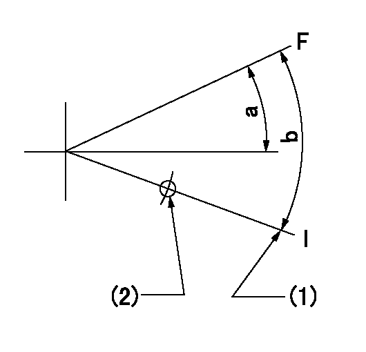
F:Full speed
I:Idle
(1)Stopper bolt setting
(2)Use the hole at R = aa
----------
aa=135mm
----------
a=(4deg)+-5deg b=(15deg)+-5deg
----------
aa=135mm
----------
a=(4deg)+-5deg b=(15deg)+-5deg
0000000901
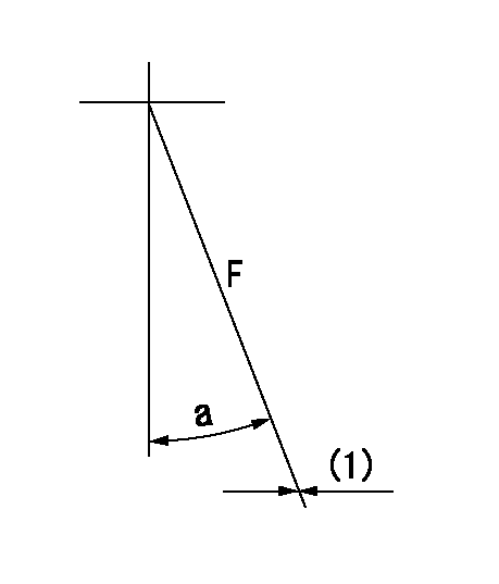
F:Full load
(1)Fix using the stopper bolt.
----------
----------
a=15deg+-5deg
----------
----------
a=15deg+-5deg
Stop lever angle
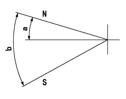
N:Pump normal
S:Stop the pump.
----------
----------
a=28deg+-5deg b=71deg+-5deg
----------
----------
a=28deg+-5deg b=71deg+-5deg
Timing setting

(1)Pump vertical direction
(2)Position of damper's threaded hole at No 1 cylinder's beginning of injection
(3)-
(4)-
----------
----------
a=(8deg)
----------
----------
a=(8deg)
Information:
Section A:
Rotation (seen from the drive end) ... counterclockwise Test on test stand, with SAE 10W oil at 120° F (49° C) Output ... 51 U.S. gpm(193 liter/min) with pump at ... 2550 rpmSection B:
Rotation (seen from the drive end) ... counterclockwise Test on test stand, with SAE 10W oil at 120° F (49° C) Output ... 72 U.S. gpm(272 liter/min) at a pressure of ... 45 psi(310 kPa)with pump at ... 2550 rpmOutput ... 38 U.S. gpm(144 liter/min) at a pressure of ... 81 psi(560 kPa)with pump at ... 2550 rpm Scavenge pump end (Section A)(1) Diameter of drive shaft and idler shaft (new) ... .8000 .0002 in.(20.320 0.005 mm) Bore in bearings for drive shaft and idler shaft (new) ... .8016 .0003 in.(20.361 0.008 mm)(2) Length of gears (new) ... 2.2503 .0010 in.(57.158 0.025 mm) Depth of bores for gears (new) ... 2.2553 .0008 in.(57.285 0.020 mm) Spacer assembly(3) Diameter of drive shaft and idler shaft (new) ... .8747 .0002 in.(22.217 0.005 mm) Bore in bearings for drive shaft and idler shaft (new) ... .8763 .0003 in.(22.258 0.008 mm) Pump body assembly (Section B)(4) Length of gears (new) ... 3.1250 .0010 in.(79.375 0.025 mm) Depth of bores for gears (new) ... 3.1300 .0008 in.(79.502 0.020 mm)(5) Diameter of drive shaft and idler shaft (new) ... .8747 .0002 in.(22.217 0.005 mm) Bore in bearings for drive shaft and idler shaft (new) ... .8763 .0003 in.(22.258 0.008 mm)(6) 2S2760 Spring (oil pressure relief valve): Length under test force ... 4.64 in.(117.9 mm)Test force ... 110 6 lb.(490 27 N)Free length after test ... 6.02 in.(152.9 mm)Outside diameter ... 1.063 in.(27.00 mm)
SCAVENGE PUMP(7) Bearing junction.(8) Position of bearing junction from the centerline through bearing bores ... 30° 15°(9) Install bearings in bottom of gear bores to a depth of ... .060 .010 in.(1.52 0.25 mm) Rotation of pump must be free when turned by hand.

