Information injection-pump assembly
BOSCH
F 01G 09U 1J6
f01g09u1j6
ZEXEL
106681-4490
1066814490
MITSUBISHI-HEAV
34A6500150
34a6500150

Rating:
Service parts 106681-4490 INJECTION-PUMP ASSEMBLY:
1.
_
2.
FUEL INJECTION PUMP
3.
GOVERNOR
4.
SUPPLY PUMP
5.
AUTOM. ADVANCE MECHANIS
6.
COUPLING PLATE
7.
COUPLING PLATE
8.
_
9.
_
11.
Nozzle and Holder
12.
Open Pre:MPa(Kqf/cm2)
17.2(175)/24.4(300)
15.
NOZZLE SET
Include in #1:
106681-4490
as INJECTION-PUMP ASSEMBLY
Cross reference number
BOSCH
F 01G 09U 1J6
f01g09u1j6
ZEXEL
106681-4490
1066814490
MITSUBISHI-HEAV
34A6500150
34a6500150
Zexel num
Bosch num
Firm num
Name
106681-4490
F 01G 09U 1J6
34A6500150 MITSUBISHI-HEAV
INJECTION-PUMP ASSEMBLY
S6B3-MTK2 K
S6B3-MTK2 K
Calibration Data:
Adjustment conditions
Test oil
1404 Test oil ISO4113 or {SAEJ967d}
1404 Test oil ISO4113 or {SAEJ967d}
Test oil temperature
degC
40
40
45
Nozzle and nozzle holder
105780-8130
Bosch type code
EFEP215A
Nozzle
105780-0050
Bosch type code
DN6TD119NP1T
Nozzle holder
105780-2090
Bosch type code
EFEP215
Opening pressure
MPa
17.2
Opening pressure
kgf/cm2
175
Injection pipe
Outer diameter - inner diameter - length (mm) mm 8-4-1000
Outer diameter - inner diameter - length (mm) mm 8-4-1000
Overflow valve
131425-1720
Overflow valve opening pressure
kPa
255
221
289
Overflow valve opening pressure
kgf/cm2
2.6
2.25
2.95
Tester oil delivery pressure
kPa
157
157
157
Tester oil delivery pressure
kgf/cm2
1.6
1.6
1.6
Direction of rotation (viewed from drive side)
Left L
Left L
Injection timing adjustment
Direction of rotation (viewed from drive side)
Left L
Left L
Injection order
1-5-3-6-
2-4
Pre-stroke
mm
2.8
2.75
2.85
Beginning of injection position
Governor side NO.1
Governor side NO.1
Difference between angles 1
Cal 1-5 deg. 60 59.5 60.5
Cal 1-5 deg. 60 59.5 60.5
Difference between angles 2
Cal 1-3 deg. 120 119.5 120.5
Cal 1-3 deg. 120 119.5 120.5
Difference between angles 3
Cal 1-6 deg. 180 179.5 180.5
Cal 1-6 deg. 180 179.5 180.5
Difference between angles 4
Cyl.1-2 deg. 240 239.5 240.5
Cyl.1-2 deg. 240 239.5 240.5
Difference between angles 5
Cal 1-4 deg. 300 299.5 300.5
Cal 1-4 deg. 300 299.5 300.5
Injection quantity adjustment
Adjusting point
A
Rack position
15.1
Pump speed
r/min
1035
1035
1035
Average injection quantity
mm3/st.
487
478
496
Max. variation between cylinders
%
0
-3
3
Basic
*
Fixing the lever
*
Boost pressure
kPa
93.3
93.3
Boost pressure
mmHg
700
700
Injection quantity adjustment_02
Adjusting point
C
Rack position
8.2+-0.5
Pump speed
r/min
350
350
350
Average injection quantity
mm3/st.
24
21
27
Max. variation between cylinders
%
0
-10
10
Fixing the rack
*
Boost pressure
kPa
0
0
0
Boost pressure
mmHg
0
0
0
Boost compensator adjustment
Pump speed
r/min
750
750
750
Rack position
R1-3.2
Boost pressure
kPa
33.3
30.6
36
Boost pressure
mmHg
250
230
270
Boost compensator adjustment_02
Pump speed
r/min
750
750
750
Rack position
R1(15.1)
Boost pressure
kPa
80
73.3
86.7
Boost pressure
mmHg
600
550
650
Timer adjustment
Pump speed
r/min
(N1+50)-
-
Advance angle
deg.
0
0
0
Remarks
Start
Start
Timer adjustment_02
Pump speed
r/min
N1
Advance angle
deg.
0.5
Remarks
Measure the actual speed.
Measure the actual speed.
Timer adjustment_03
Pump speed
r/min
-
Advance angle
deg.
2
1.5
2.5
Remarks
Measure the actual speed, stop
Measure the actual speed, stop
Test data Ex:
Governor adjustment
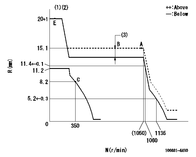
N:Pump speed
R:Rack position (mm)
(1)Target notch: K
(2)Tolerance for racks not indicated: +-0.05mm.
(3)Boost compensator stroke: BCL
----------
K=15 BCL=3.2+-0.1mm
----------
----------
K=15 BCL=3.2+-0.1mm
----------
Speed control lever angle
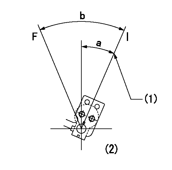
F:Full speed
I:Idle
(1)Stopper bolt setting
(2)At the center of the lever key groove
----------
----------
a=16deg+-5deg b=31deg+-5deg
----------
----------
a=16deg+-5deg b=31deg+-5deg
Stop lever angle
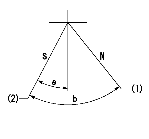
N:Pump normal
S:Stop the pump.
(1)Normal
(2)Pump speed aa, rack position bb
----------
aa=0r/min bb=1-0.5mm
----------
a=33deg+-5deg b=(73deg)
----------
aa=0r/min bb=1-0.5mm
----------
a=33deg+-5deg b=(73deg)
Timing setting

(1)Pump vertical direction
(2)Coupling's key groove position at No 1 cylinder's beginning of injection
(3)-
(4)-
----------
----------
a=(20deg)
----------
----------
a=(20deg)
Information:
Make reference to ANALYZING TURBOCHARGER FAILURE, Form No. FEG45138.(1) See TURBOCHARGER IMPELLER INSTALLATION. Do not bend or add stress to the shaft when nut is tightened.(2) Torque for bolts holding thrust plate ... 40 5 lb. in.(4.5 0.6 N m)(3) Tighten bolt holding band clamp to ... 120 10 lb. in.(13.6 1.1 N m)(4) Put 5P3931 Anti-Seize Compound on threads of bolts holding turbine housing and tighten to ... 175 15 lb. in.(19.8 1.7 N m)(5) Put 5P3931 Anti-Seize Compound on threads of bolts holding turbocharger to manifold and tighten to ... 40 4 lb. ft.(55 5 N m)(6) End play for shaft (new) ... .006 to .011 in.(0.15 to 0.27 mm)(7) Bore in the bearing ... .6268 to .6272 in.(15.921 to 15.931 mm) Diameter of surface on shaft (journal) for the bearing ... .6250 to .6254 in.(15.875 to 15.885 mm)(8) Bore in housing ... .9827 to .9832 in.(24.961 to 24.973 mm) Outside diameter of the bearing ... .9780 to .9785 in.(24.841 to 24.854 mm)(9) Clearance between ends of oil seal ring ... .008 to .015 in.(0.20 to 0.38 mm) The radial clearance for the shaft is .004 to .009 in. (0.10 to 0.23 mm).(AiResearch TV81)
(1) Nut for impeller (See TURBOCHARGER IMPELLER INSTALLATION). Do not bend or add stress to the shaft when nut is tightened.(2) Torque for the bolts that hold the backplate ... 90 10 lb. in.(10.2 1.1 N m)(3) Torque for the clamp bolts ... 10 1 lb. ft.(14 1 N m)(4) Bore in the bearings ... .6268 to .6272 in.(15.921 to 15.931 mm) Diameter for the surfaces (journals) on the shaft for the bearings ... .6250 to .6254 in.(15.875 to 15.885 mm)(5) Bore in the housing ... .9827 to .9832 in.(24.961 to 24.973 mm) Outside diameter of the bearings ... .9782 to .9787 in.(24.846 to 24.859 mm)(6) Clearance between the ends of the oil seal ring ... .008 to .015 in.(0.20 to 0.38 mm)(7) End play for the shaft ... .003 to .010 in.(0.08 to 0.25 mm)(8) Torque for support nuts (put 5P3931 Anti-Seize Compound on the stud threads) ... 40 4 lb. ft.(55 5 N m)(AiResearch T18)
Make reference to ANALYZING TURBOCHARGER FAILURE, Form No. FEG45138.(1) End play for shaft ... .0065 .0025 in.(0.165 0.063 mm) Radial clearance for the shaft ... .004 to .009 in.(0.10 to 0.23 mm)(2) Bore in the bearing ... .6268 to .6272 in.(15.921 to 15.931 mm) Diameter of surface on shaft (journal) for the bearing ... .6250 to .6254 in.(15.875 to 15.885 mm)(3) Put 8S6747 Gasket Sealer on bolts holding compressor housing and tighten to ... 105 5 lb. in.(11.9 0.6 N m)(4) Put 5P3931 Anti-Seize Compound on bolts holding turbine housing and tighten to ... 175 15 lb. in.(19.8 1.7 N m)(5) Put 5P3931 Anti-Seize Compound on threads of bolts that hold turbocharger to manifold and tighten to ... 40 4 lb. ft.(55 5 N
Have questions with 106681-4490?
Group cross 106681-4490 ZEXEL
Mitsubishi-Heav
Mitsubishi-Heav
Yanmar
Niigata-Tekkou
Mitsubishi-Heav
106681-4490
F 01G 09U 1J6
34A6500150
INJECTION-PUMP ASSEMBLY
S6B3-MTK2
S6B3-MTK2